JLM Baby Animal

GroupDIY Audio Forum

Help Support GroupDIY Audio Forum:

This site may earn a commission from merchant affiliate links, including eBay, Amazon, and others.
[quote author="TornadoTed"]I've built 4 channels with Cinemag input iron, real 2520 but with the JLM 111Dc output iron.

Just getting the cases powder coated, should be up and running in the next couple of weeks.[/quote]

Let me know how it works out because I'm very interested in going this route.
 
[quote author="Knarleybass"]
DSC01580.JPG

DSC01581.JPG

DSC01583.JPG

For the longest time I only had three up and running, I finally got the fourth in the case and working, they sound great![/quote]

I have the cases and some aluminium angle and am ready to mount the output transformers.

Are you having any problems with hum mounting the output transformers like this?

My tech suggested mounting them at 90 degrees to each other to avoid hum fields. It doesn't look anywhere near as tidy as this method but is it worth doing?
 
did anyone try this configuration ?

Ch 1: Cinemag CM-75101APC -> Cinemag CMOQ-2S -> Hybrid
Ch 2: Lundahl LL1578 -> Hybrid

or does the LL1578"XL" version have definite advantages ?
is there a reason to prefer an original 2520 (api) or JLM 99V
in comparison to the Hybrid ?

thanks
patilon
 
Hi all,

I find it very confusing there is no documentation supplied. I am building the BAD with the jlm input TX. Where can I find info about what parts are omitted with this set up?

Im probably stupid, but cant find it anywhere, and I dont know if its a good idea that there is zero documentation supplied with the kits. I mean , for just one example, what the hell is CZ load or whatever it is and what should its value be?

I at least figure some of the caps around the 99V shouldnt be used in this config as the 99V wont fit over the top of them.

Dunno, just confusing.
 
[quote author="dufo"]Hi all,

I find it very confusing there is no documentation supplied. I am building the BAD with the jlm input TX. Where can I find info about what parts are omitted with this set up?

Im probably stupid, but cant find it anywhere, and I dont know if its a good idea that there is zero documentation supplied with the kits. I mean , for just one example, what the hell is CZ load or whatever it is and what should its value be?

I at least figure some of the caps around the 99V shouldnt be used in this config as the 99V wont fit over the top of them.

Dunno, just confusing.[/quote]
Have a look at the 1st. and 2nd. yellow sheet, about half the page down http://jlmaudio.com/Baby_Animal_Mic_Pre.htm
CZ (Cap for zobel network) is not fittet.
 
I have the cases and some aluminium angle and am ready to mount the output transformers.

Are you having any problems with hum mounting the output transformers like this?

My tech suggested mounting them at 90 degrees to each other to avoid hum fields. It doesn't look anywhere near as tidy as this method but is it worth doing?

There is no hum problems mounting them like Knarleybass has done as none of the transformers are power ones. I think your tech means he is worried about coupling between channels but just keep the spacing about 1" or more apart and it will be fine.

or does the LL1578"XL" version have definite advantages ?
Not really as the normal version has enough headroom and you want some colour from the transformer. Normal LL1578 is great.

is there a reason to prefer an original 2520 (api) or JLM 99V
in comparison to the Hybrid ?

A 2520 has tight low end and is very hard edge sounding in the high end due to the large odd harmonics.
The 99v is the complete opposite with a fat low end and silky high end.
The Hybrid in class A/B has tight low end and has the fast snap of the 2520 without the high end distortion.
The Hybrid in Class A still has the tight low end but is more like the silky high end of the 99v but still a bit faster sounding.

I find it very confusing there is no documentation supplied. I am building the BAD with the jlm input TX. Where can I find info about what parts are omitted with this set up?

The BAD = Dual99v changed to run of a single 48v rail. It is the same as a normal BA kit. You fit all parts in the kit which should leave a 10k and 27k, 120R and 2 x 270R. RGAIN1 & 2 = 270R, RPAD = 120R. RL = 10k for JLM14. RL = 27k for OEP262A3C. JLM14 & OEP262A3C require no CZ or RZ. The gold pins that hold the 99v are only pushed into the PCB until the bottom of the pin is flush with the bottom of the PCB so they hold the 99v over the parts under it. Ceramic caps under the 99V are laid on there side. THE BAD has a dual 10k rev log pot which wires to the 0v which goes to both pots and G2 goes to one pot and G1 to the other half of the pot. Just like the BA overlay shows but done twice. The BAD also has a spot for a trim or output volume pot marked O = out, I = in and 0v. If not using this pot wire O to I. This point can also be used to insert a passive eq circuit like a Pultec etc.

Don't forget if you have any questions while building feel free to email me.

JLM%20FET%20DI%20400.jpg


Have a great Xmas and New Year everyone :wink:
 
I guess I should wire the JLM111DC 2:1 for the Cinemag CMMI-8PCA, API 2520 combination, correct?

What about the JLM14, JLM99v combination. 1:1 or 2:1?
 
So Joe, I see in your last post what seems to be a FET DI... Am I missing something or are you about to offer it as a kit..? If so, I think I speak for more than a few people when I say that I'm more than just a little bit interested.
 
guess I should wire the JLM111DC 2:1 for the Cinemag CMMI-8PCA, API 2520 combination, correct?

What about the JLM14, JLM99v combination. 1:1 or 2:1?
With the BA use the JLM111DC as 1:2 to get the extra 6dB gain.

So Joe, I see in your last post what seems to be a FET DI... Am I missing something or are you about to offer it as a kit..? If so, I think I speak for more than a few people when I say that I'm more than just a little bit interested.
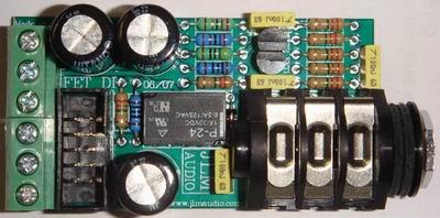
Yes the photo is the new unity gain 1Meg input discrete FET DI kit with Cliff S4 socket which can mount easily up to 1 to 5mm thick panel. It uses a relay to switch between DI and Mic when a jack is inserted. Can plug into the BA, BAD, BAN, GO between, Go between + IDC socket and run off the 48v rail just like the original JLM DI that uses the OPA2604 IC.
 
[quote author="JLM Audio"]Yes the photo is the new unity gain 1Meg input discrete FET DI kit with Cliff S4 socket which can mount easily up to 1 to 5mm thick panel. It uses a relay to switch between DI and Mic when a jack is inserted. Can plug into the BA, BAD, BAN, GO between, Go between + IDC socket and run off the 48v rail just like the original JLM DI that uses the OPA2604 IC.[/quote]

Hey Joe,

Are these availble yet? What are they going to cost and do they sound much different sonically to the original Active DI's? Good call on the new sockets, I think these will be a lot better then the old ones which were easy to mis thread if you put too much torque on them.

Any news on the PEQ EQ' you were working on a while back, the one that could plug into BAD and be used as a channel strip? Seemed kind of fun!

Cheers

Matt
 
Are these available yet? What are they going to cost and do they sound much different sonically to the original Active DI's? Good call on the new sockets, I think these will be a lot better than the old ones which were easy to mis thread if you put too much torque on them.
Yes we have kits in stock for $38AUD and they will be up on the web site by the time we start back in mid January. We will also keep making IC DI kits as well. The real reason for the redesign was the difficulty in getting 1000 x OPA2604AP with less than a 20 week wait as I mentioned to Rochey at AES. But I thought I would try to solve the socket issue at the same time. We already use Cliff S4 sockets by the 1000s for our patchbays and they have been very reliable over the years so they were the logical choice but requires a relay to do the switching since the S4 only has break contacts.

The New FET DI is a Whites Cathode Follower type circuit like the 12BH7 on the output of a LA2A but done with 2 Fets instead. It runs in 10mA of Class A and then Class A/B if more current is needed. The lower FET in this circuit is basically a constant current circuit with its input modulated so can run on 24v to 48v without any changes. The relay is a 24v 10mA type with a 2k7 resistor in series to run it from 48v so if using 24v the 2k7 needs to be changed to a wire link. The relay is normally on when no jack is inserted. The unity gain circuit has better THD than the OPA2604 at low signal to medium signal levels. Best tone description would be pure and smooth with more warmth and fatness the harder the input is driven as a 2nd Harmonic starts to appear. But in normal use I think most people would find it hard to tell the FET & IC DI's apart.
 
guys,

RZ CZ and Cload I understand are not used in the BA. Do I have to bridge these with some wire anyway though? thanks
If using the JLM14 or OEP262A3C no CZ or RZ are needed and those positions just need to be left empty. If using other transformers look at the manufacturers datasheet to see if it requires any Zobel parts. Most BA builds usually need a CL of 220pF for fixed impedance or CL of 390pF for Variable Impedance so the opamp doesn't oscillate at full gain.

Note and Errata: Current BA PCB with the date 09/07 has 2 x 0.1uF caps marked on it only one needs to be fitted. One of the 0.1uF is where CL was on the old BA PCB but is not CL. There is no CL position on the PCB so the CL cap needs to be mounted under the PCB across RL on this version of the PCB.
 
Thanks Jim,

Sorry ,yes, JLM TX in the BAD here...

I didn’t get any cap that would be used for CL in my kit. Will ceramic be ok?
Ok BAD is different to BA in that there are 2 opamp stages and we are not trying to get full gain out of each opamp. So no CL is needed with JLM14 or OEP262A3C and fixed Impedance. With variable impedance you may need a CL of 100pF to 220pF. Ceramics are fine for this.
 
Which DC connector type do I need for the "48v 380mA 18W SMPS 90v to 250v world power supply"?

I thought it was a 2.1 mm jack but that doesn't fit.

An order number would be very helpful so that I can check if I can get this type here in Germany.

Thanks.
 
Which DC connector type do I need for the "48v 380mA 18W SMPS 90v to 250v world power supply"?

The 48v 380mA power supply does indead have a 2.1mm x 5.5mm x 11mm DC connector on it.

If it fits the 5.5mm hole but will not push in you will have a 2.5mm centre pin socket.
 

Latest posts

Back
Top