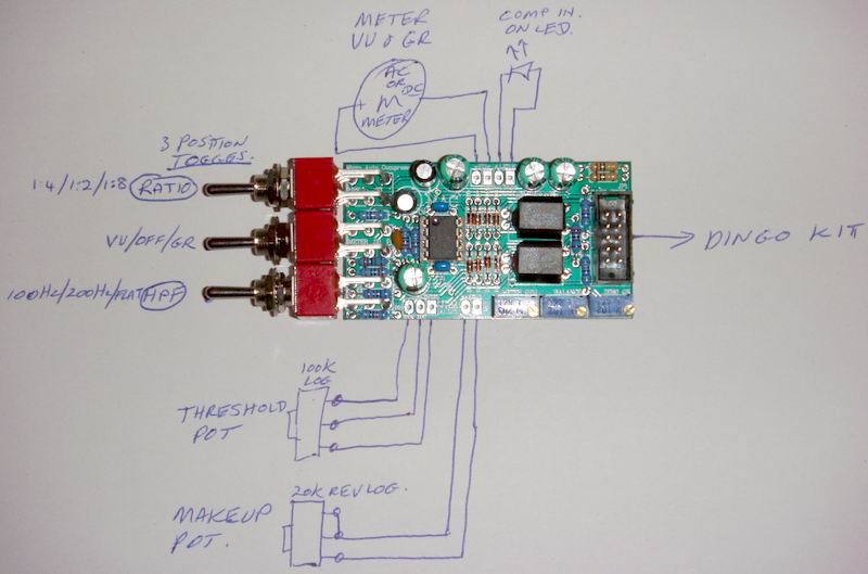
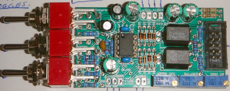
I have the BA4 'everything' kit with the JLM 1:4 input transformer and JLM 99V op amp. Before I start soldering, I have a few questions.
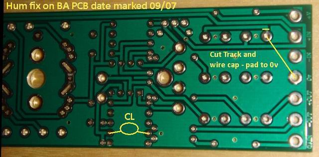
1. In the picture, components shaded red will not be populated. Components shaded yellow will be populated, but are not in the circuit in this configuration. The blue lines will be jumpered. Is this correct?
2. It looks to me like the resistor marked 1MEG on the PCB should be populated with a 220K resistor. Is this correct?
3. According to the input transformer table on the JLM Web site, CL should be 390pF. I didn't get that in the kit, but I did get 2 220pF capacitors which I don't know what to do with. What do I do?
Thanks.
Bob Miller