JLM Baby Animal

GroupDIY Audio Forum

Help Support GroupDIY Audio Forum:

This site may earn a commission from merchant affiliate links, including eBay, Amazon, and others.
That's exactly what I needed. :grin:

I souldn't have a problem testing this with either pot right?
I mean it won't screw anything up will it?


The Other question I had is how hard would it be to place a switched output trafo in. Right now they are set up as "quasi- balanced" i think Matt called it.
 
Ok, I have moved over to join in on this thread. Some of my questions are a little embarrasing so I hope someone is willing to help out. I am hoping to document the process of making some of these pre's in the hope that it may help other electrically challenged people such as myself.

Firstly

1. I am using the JLM 1:4 transformer and the JLM99V Opamp combination. It is my understanding that because I am using the outboard premade powersupply, I don't need to install the parts marked * and # Is this right?

2. I have to apparently not fit RL and CZ is that right?. CL is a 220pF (what does this look like?) RG is a 68R right?

3. 1x4 jumper pins, Do I solder all four posts in and put a jumper in the middle two for low ration in the transformer? or high?

4. Do I have to strap something over the IC Pins and the BD681 with this configuration? What do I use to wire between pins?

5. Lastly. How do you wire up the cable that runs between the dI and the preamp. What are the corrosponding coulors to pins?

Any advice would be greatly appreciated. Sorry to post so many silly questions .

Regards

Nick
 
How about stacking the pre's? Would that be a bad idea? Or perhaps a good idea with twice 99v-color and the possibility of gain staging?
No it can work fine. You will usually have to insert the pad on the second mic pre and run the main amount of gain on the first pre.

I souldn't have a problem testing this with either pot right?
I mean it won't screw anything up will it?
Either pot type will work but with different feel or smoothness to tone variation. I have given minimum in series resistances to reflect 600ohm to roughly 6k load on the tables on the web site. Going lower than that can work but have not been tested. When the PAD is switched in it will mostly override the input impedance variations but the tone may still change with the impedance control as the high end of the input transformers usually get brighter when driven into higher loads.

1. I am using the JLM 1:4 transformer and the JLM99V Opamp combination. It is my understanding that because I am using the outboard premade powersupply, I don't need to install the parts marked * and # Is this right?
The parts fitted depend on which outboard SMPS supply you are using and for the large one which voltage you have set it to. I know you have the 48v small supply so no * or # parts need to be fitted. But both BD681 positions have to have C the centre pin linked to E.

2. I have to apparently not fit RL and CZ is that right?. CL is a 220pF (what does this look like?) RG is a 68R right?
I think you have typed that wrong as RZ & CZ are not needed. The other 2 values are right.

3. 1x4 jumper pins, Do I solder all four posts in and put a jumper in the middle two for low ration in the transformer? or high?
The JLM14 has no ratio jumper fitted to the PCB as it is always 1:4 ratio.

4. Do I have to strap something over the IC Pins and the BD681 with this configuration? What do I use to wire between pins?
Use a cut off component leg.

All the answers to questions 1 to 4 can be found on the Baby animal page in the tables. http://www.jlmaudio.com/Baby_Animal_Mic_Pre.htm

5. Lastly. How do you wire up the cable that runs between the dI and the preamp. What are the corrosponding coulors to pins?
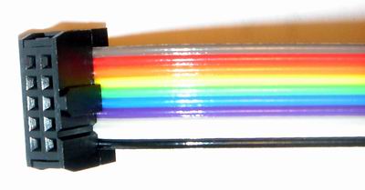
Brown is pin 1 on the ribbon cable which is marked by a triangle on the IDC connector. So the ribbon cable can be put in either side of the connector as long as both connectors have the same colour at pin 1 end. A small bench vice or vice grips can be used to crimp the IDC connectors down. And then the extra cable clamp can be put on by hand.
 
Hey, Nick! Looks like Joe already got you. One thing that's worth mentioning is when you have a question, it's a good idea to also mention what PSU you are using. Looks like you are using the 48v.

As Joe mentioned, you can strap the IC and BD681 by simply using any bit of component lead that you've clipped off of a resistor or cap that you've already installed. In the case of the IC, I installed the DIP even though I am using the 99v opamp. I took a spare lead (of which there were plenty lying around the table by that point!), cut it to size, bent it at either end and inserted it into the DIP. That way I don't have to solder the lead across the back which can be tricky in that spot. You can use the datasheet (now linked to from my first post on page one) to see which pins are which.

For a hint with the ribbon cable, check Mr. Jones' pictures at the top of page 6 of this thread. Important thing is that whatever color corresponds to pin one on the pre, that it is the same at the DI end. Before clamping the connectors down, just set the pre and DI up side by side and get it set it up.
 
Thanks guys very much! I have almost completed my first kit. A couple more questions and I should be right.

1. If I am mounting the 99V opamp do I still use the 8 pin opamp socket? If I put this in, the opamp legs don't poke through enough to make a good solder it seems. If I don't use it should I be raising the opamp above the components underneath so nothing is touching or is it ok to rest it on parts on the board?

2. Still curious to know what does the 220pF look like that has to go in CL?

Thanks so much for your help again. I am going to post my pictures soon as I get the case and mount a preamp :)
 
1. If I am mounting the 99V opamp do I still use the 8 pin opamp socket? If I put this in, the opamp legs don't poke through enough to make a good solder it seems. If I don't use it should I be raising the opamp above the components underneath so nothing is touching or is it ok to rest it on parts on the board?
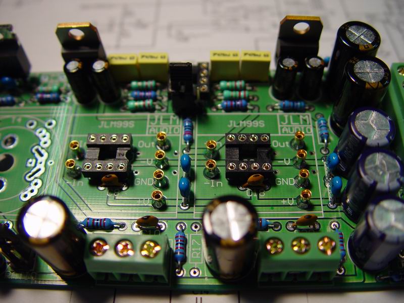
For DIY it is not the best idea to solder in the 99v opamp as it makes any fault finding difficult. Use the 6 supplied gold sockets for the 99v which should be pushed into the PCB so the bottom of the socket is flush with the bottom of the PCB. Then solder around the gold socket and the PAD on top of the PCB. This should make the 99v plug in and sit just above the DIP8 if it is fitted. With the DIP8 and gold pins fitted and 48v power rail you can swap from JLM99v to OPA2604AP to hear the difference in sound easily.

2. Still qurious to know what does the 220pF look like that has to go in CL?
It is a small ceramic cap just like the two 47pF ones
 
What do these gold sockets look like Joe? I didn't have any spare parts exept for Jumpers, leftover * and # pieces, a circular black plastic plug( not sure about that one either.

I have a feeling I may not have received these hence my confusion with the mounting of the opamp. Were thay supposed to come in the bag with the preamp bits, bag with the trasformers or the bag with the Power supply socket and transformer mounts?

Thanks
 
This is a picture of JLM's dual 99v but it shows the sockets that should've been supplied and what they look like.

JLM99XMB%20IC%20Sockets.jpg


They were in the baggie that the op amps came in when I got them. If you didn't get them email Joe.

Hope that helps.

p.s. When you install them, make sure they aren't leaning in any one direction. This makes it tough to place the op-amp. :grin:
And yes, I almost found this out the hard way. Almost! :oops:
 
When I recieved my kit, the gold sockets were on the legs of the 99v opamp. Check to see if your opamp has them on it. If it does, just pull them off, and fit them onto the PCB as Joe described. If your 99v has gold pins, that's them. Pull 'em off. The real pins on the 99v are inside :grin:

True, the legs of the DIP don't fit as far through the board as the other components. It helps to have some sort of helping hand tool. I use both a "helping hand" with alligator clips AND a panavise together (although stuffing the board I only really need a panavise). As I recall, I very carefully clamped the PCB and DIP together so I could solder one leg of the DIP. Once I did that, the solder held the DIP in place so I was able to put the PCB back in my vise so that the whole back of the board was exposed, allowing me to solder the rest of the pins.

You can often get the panavise at Fry's (if they are in your area), or maybe a good hobby shop. You can see it in some of the pictures I posted in this thread (a greyish base with a black "C" clamp on it).
 
One the list of parts it sais (1 x 180pF) (2 x 47pF ceramic cap)

I assume the 47pF are the greay caps with a black tip which I have installed. If thats the case I have 3 of those ( is the extra one a spare?) and 1 other ceramic cap thats white with a yellow top ( I think it sais R18 on it.

Why does the parts list say 180pF. Is it supposed to be 220pF?

If you say CL is just like the other ceramic caps, do you mean exactly the same or the same type of cap but different colour? ie the white one with yellow tip?

Thanks again guys
 
I just looked through the other kits and it seems there may have been one extra 47pF in the bag I was using. The others have 2. Therefore I will assume the other ceramic cap (white and yellow) is CL

Thanks
 
Ok another question. Everything has been done except for the cable that runs between the D.I and preamp. I understand the orientation and that they must both correspond to pin 1 at both ends but.....

How does this clip work? Do I solder these wires onto the little metal prongs on the clip ? I am also wondering, do I start with brown and work up on apposing sides or run up one side and down the other.

God I'm sounding crazy...how embarrassing :) Does anyone understand what I am asking or am I too unclear?

Regards

Newbie Nick
 
Is it difficult to modify the BA PCB for dual supplies (can't see a jumper there)? I guess using Dremel makes sense, and there seems to be enough big caps onboard, maybe a small resistor (10 ohms for V-) and an extra bypass cap are needed? Looking schematics swapping 1/2v and GND connections at some point and leaving out the 10k resistors for that 1/2v is all you need.
 
Thankyou so much for the pics but what about prior to assembling this clip. How do the wires connect to the prongs. Do I solder them? Thanks guys :)
 
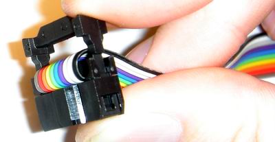
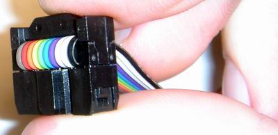
No soldering. When you clamp the two pieces together as shown in the top two pictures, several "blades" cut into the ribbon cable and make their connection. Then fold the ribbon back and clip the top piece on as shown in the third and fourth photos.

Print out the pics and perhaps a few pics of some of the builds that have been done and put them out on your workbench. Get your ribbon cables and their connectors together and "practice" assembling them as shown, without fully clamping them down. You'll get it. I did it this way.

When the cables are done and laying flat on the table, one connector will be facing down and the other facing up toward you. Play with it a few times, it will start to make sense.

Thanks for the photos, Matt!
 
I see the light!! Thanks, can't believe I thought I had to solder it all. Awsome.

I now doing the other preamp with the OEP A262A3C transformer. Is it ok if I don't use a mount (can't see one) and just solder it in at least 1mm off the PCB.

Thanks again

I am starting to get the hang of this :)
 
Back
Top