JLM Baby Animal

GroupDIY Audio Forum

Help Support GroupDIY Audio Forum:

This site may earn a commission from merchant affiliate links, including eBay, Amazon, and others.
Hi again,

I got everything just about put together on one of the BA'a last night. Thanks go out to everyone for the soldering suggestions. It really helped.

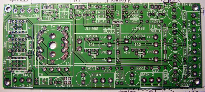
The boards are laid out very nicely. Things fit like a glove.

"WONDERFULLY DONE MR. MALONE." Very impressive! :!:
Now if I can actually make it work! :oops:

Everything went pretty well except for a few mishaps. The one I am concerned with is:

-- When I pushed one of the 47pf caps into the board it went a little too hard and slightly cracked the outer coating just above one of the leads. Not major but the crack is visible.
Is it destroyed or is it going to cause any other problems such as noise?

I have some other questions that I would also appreciate some help with:

(1) The regulator has BD681 on the left side (if facing metal side of reg). Is this the "B" side and the right side (that I think says "ON") the "E" side?

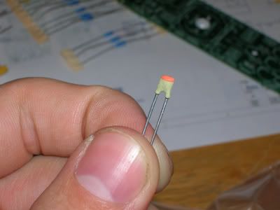
(2) Even after reading the posts here I am still confused with which cap is the 220pf and which is the 0.1uf?
One is yellow with a darker yellow top on it and has the numbers (I think) either 81u or is it n18 with straight leads.
The other is smaller and more orange in color and has 104 (I think) and the leads are already bent.
Which is which?

(3) Since I am going with the higher voltage I installed the *47v zener. I assumed they were the bigger red one's since 2 are supplied and there were 2 of those that were the same.
Correct?

-- And installed it with the black lined side facing the thicker lined side on the board print which would be facing to the right?
Is that correct?

(4) I have the larger pw supply. I am assuming the side of the wire coming off of it that has the bumpy's is the positive?

(5) I assume that any square pad on the board is pin "1" for any of the IC sock, IDC sock, and transf jumper pins?
IDC sock pin "1" has the "V notch"?


Oh! What is the 27k resistor for? I couldn't find what it was used for.

I know this is a lot of questions but I looked through all of the posts here and didn't find the answers to these questions. I did have others (e.g. transf hookup) and I found the answers to those here.

Thx,

Tammy
 
Why does the parts list say 180pF. Is it supposed to be 220pF?
mysterycap.jpg

CL can be 180pF or 220pF. The 47pF, 180pF or 220pF should be small grey types as shown above. All values may either have black or orange top strip. There actual values are written on the side but you need a good eye and bright light to see it. Some early kits had a normal orange disc ceramic 180pF or 220pF. Some K types are more like a flat square and white/yellow in colour. But the main thing is to find the value on the side. n18 = 0.18nF = 180pF

MonoCap.jpg

All 0.1uF mono caps look like the above but may be blue or yellow. 104 = 0.1uF.

Is it difficult to modify the BA PCB for dual supplies (can't see a jumper there)?
Yes it is difficult but not impossible but you would have to ask why since you would need a +/-V and 48v power supply. But would be easier to use the JLM99*MB PCB for +/- rail designs like the Dual 99v uses as shown below. http://www.jlmaudio.com/JLM99v.htm

JLM99XMB%20blank.jpg


I am getting lots of questions about how can a opamp run on one rail. The opamp is still running on +/-V but in a tricky way. The +/-V rails are half the power supply rail if no opamp reg fitted or roughly half the # zener volts minus 1.2v when opamp reg is fitted. Example # zener is 33v - 1.2v / 2 = +/-15.9V for 2520 or 1731 etc.

I now doing the other preamp with the OEP A262A3C transformer. Is it ok if I don't use a mount (can't see one) and just solder it in at least 1mm off the PCB.
I use two small cable ties under the transformer while soldering it in. Then slide them out after it is soldered.

The way it sounds it is kind of important to have the components as close and tight to the board as possible?
No not at all. We only do it for neatness but it will not affect the sound if it isn't neat.

Does reheating the joints then moving the part set up a greater possibility for a cold joint?
Yes if you are a beginner I would not recommend reheating solder joints.

with 48v power CZ and RZ are irrelevant as are resistors marked * and # RL is a 10k ?
CZ & RZ have to do with transformer loading not power rails. Just the transformers we show on the sight do not need zobel taming. But others that fit the PCB might need them. RL depends on the transformer load needed. Look at the tables here http://www.jlmaudio.com/Baby_Animal_Mic_Pre.htm

RP states 100R ?
For 20dB pad RP can be 100R or 120R as it will only make about half a dB difference.

I've seen people using shielded cable for this, good/bad?
Not needed so much in the baby animal because it only has 60dB of gain but with higher gain like the dual 99v it can stop some oscillation problems.

Is it destroyed or is it going to cause any other problems such as noise?
The caps do make the paint flake off the pins when the legs are bent out to far but it should be fine.

The regulator has BD681 on the left side (if facing metal side of reg). Is this the "B" side and the right side (that I think says "ON") the "E" side?
If in doubt Google the part number http://w3.id.tue.nl/fileadmin/id/objects/E-Atelier/doc/Datasheets/Transistoren/BD679A.pdf. So looking from the front plastic side pins go left to right E C B.

Since I am going with the higher voltage I installed the *47v zener. I assumed they were the bigger red one's since 2 are supplied and there were 2 of those that were the same. Correct?
The 500mW zeners are BZX79 or 55 types so to work out the volts you just just need to read the 2 digits after the letter C. eg C30 = 30v, C33 = 33v, C36= 36v, C47 = 47v. We have been having trouble getting the 500mW 47v types so have been supplying 1watt types which are 1N4756A = 47v.

-- And installed it with the black lined side facing the thicker lined side on the board print which would be facing to the right?
Is that correct?
Yes.

I have the larger pw supply. I am assuming the side of the wire coming off of it that has the bumpy's is the positive?
Always use a multimeter just to be sure.

I assume that any square pad on the board is pin "1" for any of the IC sock, IDC sock, and transf jumper pins?
IDC sock pin "1" has the "V notch"?
Yes.

Oh! What is the 27k resistor for? I couldn't find what it was used for.
Load resistor for OEP262A3C or E.
 
Thanks for the answers Joe. I think I am clear on everything up to this point.

I have everything just about done and hopefully will be testing them out within a few days.

Tammy
 
Hey Guys,

I'm hoping those of you with your kits can help me out here.

I'm looking for the measurements of the 10K REV LOG pot. I'm working on a panel and need to figure out how wide to drill the hole while I wait on my kits. Can someone measure this for me, first the width of the panel mounted bushing, then the width of the pot shaft (need to figure out what pots to use) and lastly the length of the pot shaft from the top of the bushing.

Thanks

Matt
 
The 10k rev log pot in the kit is a standard 16mm pot and needs a 7mm panel hole. It has a 6mm diameter 18 teeth knurled spline shaft. The Length of the bush and shaft together is 15mm. If putting a grub screw knob on the shaft put a small piece of 1mm metal in the slot in the shaft first.

Thanks everyone the Baby Animal kits sold past the 100 mark early this week :sam:
 
Some pics of my panel lettering:
15dkl11.jpg

15dknmg.jpg

15dknxj.jpg


The lettering is rub-on letters available from STAPLES (or was it Office Depot??). Clear gloss spray-paint on top of that. The letters cost around $3, the paint I had already. We'll see how long they last, but they seem to be pretty durable right now...
 
So, I'm a little late here. I got my kits ages ago, but have been rather busy. Anyway I have just about finished stuffing the boards.

I have one small problem (so far :grin:). I am unsure what value to use for RL, Joe's site mentions variable impedance (I guess that means the gain pot) as untested for the OEP262A3C tranny that I am using.

Also, to be honest, I don't even know if I should go for higher or lower tranny gain (by setting the jumpers):shock:. My mics at the moment are a KSM44 (which has an output impedance of 150 ohms), SM57's, SM58's and a dynamic Sennheiser. Does this have a bearing on tranny gain setting?

Does high/low gain setting change the character of the sound?

Ah, that was two problems :grin: anyway any guidance would be most welcome.

Neil
 
Use 27k for the load resistor, and play with the ratios and see which one you prefer. You will notice a change in sound as well as level and its really just a matter of taste as to which you prefer and decide to stick with.


M@
 
I got my Baby Animals in the mail yesterday and they're coming together nicely! One question...what do I do with the Trim pin on a 1731/2520? There is a 10k resistor in the way and I don't want to bend the pin or cut it off. Suggestions? Maybe mount the 10k on the underside of the board?
 
Has anyone heard the Baby Animal A-B'd between an OPA2604 and the JLM99v. I've got 2 99v+JLM14; 1 Hybrid(A/B)+OEP; 1 99v+OEP. I'm putting them in cases tues or wed. The thing is I've been curious if I should look into the OPA2604+OEP as a fifth or if I should add one more of the Hybrid/OEP or 99v/OEP so that I have a second stereo pair? I like having as many options as possible but having a another stereo pair gives me a lot of options too. Any ideas? Help me spend some money. :grin:
 
So here I am thinking I'm all hot sh*t for building 4 BA's and what happens when I plug the first one in? Blow a resistor up. Yup. Me in my newbie haste didn't notice the 330 cap mixed in with the rest of those big caps. I think I placed it in the wrong spot and placed a 470 there and placed the 330 in a 440 spot. So I've now taken the cap out and am out side smoking to calm down. Could this have blown the 10 ohm resistor?
Help please! :grin:
 
OK , so after hunting down a bad resistor and a bad solder joint I finally finished the BA with the jlm14 and 99v . So far I like it . Im trying to determine its sweet spot and figure out its true character . To me it has a nice clear midrange punch , not quite as deep and sweet as the hardy M1 but miles above a makie . It seemed to clip sooner than anything . It has a nice mid thing that I plan to futz more with . It would be great to hear other peoples opinions about the applications of the baby Animal

Thanks to joe and matt for a cool preamp
 

Latest posts

Back
Top