JLM VU Buffer Troubleshooting Help! (Finished w/ Pics!)

GroupDIY Audio Forum

Help Support GroupDIY Audio Forum:

This site may earn a commission from merchant affiliate links, including eBay, Amazon, and others.

ytsestef

Well-known member
Joined
Jul 2, 2009
Messages
192
Location
Athens, Greece
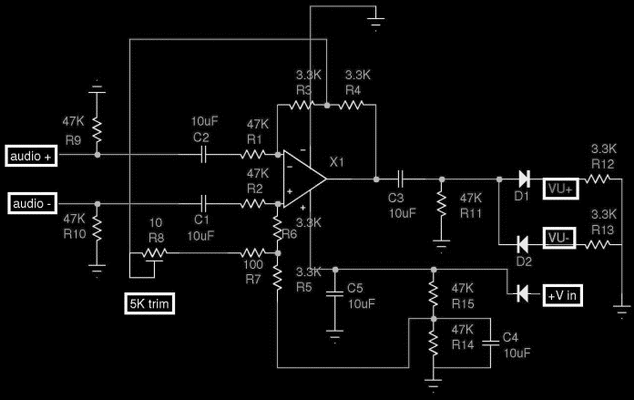
Hey everyone! I started building a 2ch VU Buffer on a single veroboard (containing both channels and PSU). PSU works fine, got +12V on TL071 VCC but the needles won't move at all (except when I turn the PSU on/off where there's a voltage spike - although that indicates that meters themselves are fine, so it must be the circuit). Both channels behave exactly the same way which makes me believe it is a design problem (I mean the veroboard layout, not the circuit design) or a wiring messup that I did due to lack of understanding (as opposed to "absent minded" or "careless"). Where can I start troubleshooting (I only have a polymeter). Here is the scematic and the veroboard layout I came up with:
VU%20Buffer%20Circuit.gif

313507q.jpg


The capacitor polarities are OK.

Thanks everyone
 
TL071 seems connected wrong.  From your layout picture, you have V+ going to pin 6, which is output, and taking your output form pin 7, which is V+. How did you make that veroboard image?  pretty cool.
 
DAMN!!!! What a noob mistake!!! And to think I knew the pinout and "carefully planned out the connections"! I triple-checked it! Well, that was lame. Thanks A LOT for your reply Dimitri!  ;D  ;D The layout is done with DIY Layout Creator, a freeware multiplatform app (Java, hence the multiplatform :) ). Can be found here: http://code.google.com/p/diy-layout-creator/

I'm off to correct this, I'll know in about 20' whether my opamps still work (thank god I bought 4 of them) :p
 
Don't worry, I make these kinds of mistakes all the time!  ;D 

Thanks for the link! Looks like an awesome piece of software! Been wanting to make some vero guitar pedals (and a Bo DI) and this is just the ticket!

Good luck!


Well, it worked... kind of. The meters move, though they are VERY, VERY jumpy. I put an 100uF cap across the VU terminals to smooth out the needle response, still very jumpy. I tried 220uF, somewhat better, but still when trying to calibrate with a sine wave @ 1kHz the best I can do by adjusting the trimpot is make it rapidly jump around -2 to +2 dB. Also the response is not at all linear, the meter acts like there's a threshold below which they don't move at all. For instance, I can't get them to smoothly move in the -20 to -10 area, they will stop at resting position and every other kick / loud part of the song they will start hitting -7 and above. Should I increase even more the cap value? Or is the problem somewhere in the circuit?
 
Nope, tried 470uF, same thing, just slower (too slow, actually). I don't think its the meters themselves, because I have used some behringers (cheaper than these) in my gssl, they work fine. Could it be the opamps? The PSU seems ok and I can't find any other mistakes in the circuit...
 
sorry I should have caught this before.. 4 eyes are better then 2 usually, I wear glasses though, never seemed to help...

check your inputs, and the TL0 pinout.

While you're at it, check everything else over, there may be other little things. As you can see I tend to miss stuff... Are these DC meters or AC meters btw? DC would need the rectification, AC should have the rectifier built in.
 
Both seem fine ???
I didn't have any BAT85 diodes (couldn't find either) and put 1N5819 (I read it's a replacement), though I do recall Joe saying that for some meters 1N series won't do. Come to think of it, the bouncing needle seems like a rectification symptom. What do you think?
 
You have the + and - input reversed at the TL071. Look at the pinout and the schematic. Audio + goes to inverting input, you have it going to non-inverting. Wasn't meaning to be cryptic or anything. Hope that fixes it for ya.. I'll look it over again once again, but if the problems persist, it would be good if you updated the vero image.
 
Says IN- goes to pin2, which is how it's wired right now...
you are confusing the opamp pin markings with the circuit markings. The pinout + and - in tell you where the inverting and non-inverting inputs of the opamp are, which are not necessarily where the + and - audio ins go to.  On the schematic, the + audio in goes to the - opamp in, and vice versa.
 
OK, got it! What if I flip pin2 and pin3 connections on the opamp? So that junction of R1 and R3 goes to pin 2... Moving multiple components is hell when working on veroboard...
 
Worked like a charm! Thanks a lot guys! Now let's see where I put the dremel and the spraypaint... hehehe :p

PS: Regarding calibration, if I remember correctly 1kHz Sine @ -20dBFS should read 0dB on the VU, right?
 

Latest posts

Back
Top