JTM45 Build with 6P3P output tubes and GZ34

GroupDIY Audio Forum

Help Support GroupDIY Audio Forum:

This site may earn a commission from merchant affiliate links, including eBay, Amazon, and others.
@Spencerleehorton
Another question that springs to mind is how to do the heater wires, there seems to be some difference of opinion in wether to twist them and have them 90 degrees to other wires or have them come in from above and be in parallel next to each other which is claimed to be better to reduce noise!
I wondered what your opinion was?
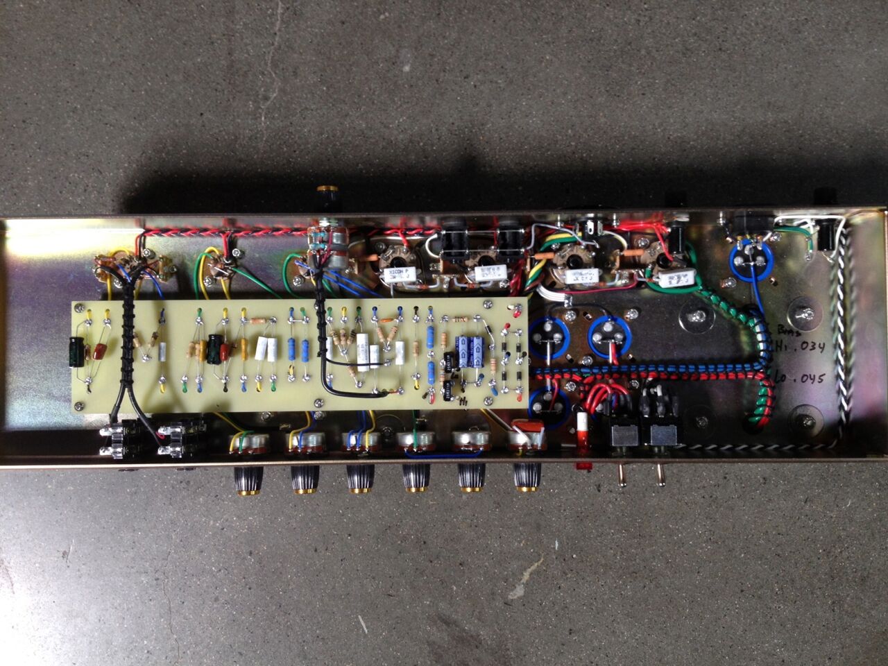
Read the Merlin Blencowe’s Article about the Heater / Filament Supplies

Keep in your mind that “Boutique” options like the DC Heaters that Boutique Amps like Metropoulos Amps aka MetroAmps uses, demands Boutique and expensive Power Transformers like Mercury Magmetics P4550JT-G2M for the DC Heaters …

So, in the most cases the realistic choices that you have to do, it is not just a “theoretical approach” about “what is the best…” in our humble opinion, but rather an economical realistic condition about what Power Transformer you could have in your hand…
 
I twist the wires from the transformer and take it around the corner of the chassis to the one of the output tube bases , then run two heavy solid cores across to the other tube base , then twisted stranded wire out to the pre-amp tubes . Looping the wire up and over to preamp tubes usually works for me but sometimes I lay it flat to the chassis also .
 
This has definitely made me want to revisit my other plexi and make sure the heaters are done correctly.
Several different ways to do it but it seems to have 2 x 3.15v CT and connect CT to audio gnd is ideal but I will try a few different things as I seem to remember it was just 6.3v, so would need to do a CT with 2 x 100R resistors.
 
(according to my novice understanding) think about what the tube designers did inside the tube, using distance and relative orientation (of the heaters (particularly if AC) and the high impedance (thus noise sensitive) grids), and try to do the same outside the tube for the wires going in. Send and return legs of the heaters together (so at least in parallel, or go further and twist) plus try to keep them apart from the grid (especially) plus other wires and in a relative orthogonal/right angle sort of orientation to each other. Going over or on the side (to me) I think it can be the same thing in the sense that going over should still place the heaters up against the "chassis" by way of the alu foil or flashing glued or stapled to the cab on the open side (which should have a low impedance connection to the rest of the chassis).

FWIW Soldano SLO100 (a high gain amp) has paralleled bus bars for the (AC) heaters and the other wires going over and in via the socket pins in a mostly right angle (or -ish) orientation relative to those heater wires:

001-4-jpg.9867


(Interestingly Mike Soldano apparently had to change to DC heaters due to problems with more recently manufactured tubes.)

This one (Suhr's version of a vintage Plexi--SL68) might be a reference to copy (since the same Marshall-style amp) :

zLsTnOs.jpeg


(another pic of a Suhr up a bit closer) :

53303143493_94388060ea_k.jpg


Also, this article looks excellent:

https://dalmura.com.au/static/Hum article.pdf
 
Strength of radiation is related to square of the distance between the transmitter and receiver: so a tight twist and maximizing distance between heater wires and sensitive pickup nodes (e.g. grids) will get you most of the way there.

Practically this shows up as two different styles: one where the heaters lay flat on the chassis, and input connections fly up through the air and land "down" on the tube sockets. The other is the heaters are flown up on the air and fly "down" to the sockets, and the other tube socket connections are laid against the chassis and connect directly. The second style is what I end up using most of the time.

Twist or parallel might be a distinction between AC and DC, as if you are running all DC heaters, there isn't much point in twisting other than (maybe) cleanliness of the install.
 
(perhaps it'll survive since there isn't much voltage there at the cathode, but) the alu electro cathode bypass for the first stage looks backwards (assuming you're going to connect the input jack side turret to ground).

Also (my understanding) using the traditional Marshall layout with the insulated jacks makes the amp more susceptible to RF. FWIW Cliff makes a "earth grounding washer" part FCR14422 (I guess you could DC ground directly at the input or perhaps use a ceramic cap with short leads direct to chassis) :

https://www.cliffuk.co.uk/products/jacksockets/s2.htm
Yes you spotted correctly!! Thank you!!
 
powered up this today and no smoke, all tubes come on and some voltages looked ok, but nothing out of the output transformer!! it was obviously a broken one, oh well didnt cost me anything, it was out of a line 6 tube amp, order a JTM45 output transformer and will install.
hopefully all will be well!?
 
@Spencerleehorton

Man, don’t be miserable “cheap-y” with your Output Transformer(s), after all the Output Transformer is a basic element in any tube amplifier that determinates your tone…

Order and install properly any decent “Radiospades type” JTM45 Output Transformer from any decent Transformer Company out there and thankfully you will get a very good “British voicing” tone for starting point…

After all, it will be a shame for you as a British not to make this legendary British Amplifier to sound as legendary as it should be sound!...
 
could you explain how full wave rectifier with CT will get me close to 320v with 2 x 190vac please?
No one said it explicitly, but full-wave bridge rectifiers give you double the voltage of full-wave rectifiers.
I have an option to get a mains txf with 580v ct, so 2 x 290v rather than the 2 x 350v.
I wondered what the result would be?
I believe as a rule, if the tubes are biased correctly, more voltage on the plates means more headroom. Biasing with lower plate voltages gives you sooner breakup. This isn't a master volume amp, so if you bias V2 or V3 for low headroom, or increase the size of your filter resistors before these stages to lower B+, it will make it easier to overdrive the preamp section (with signal from the preceding stage) while the output tubes stay clean.

There's a post somewhere on the Marshall forum about the sound differences of cold vs hot biasing of preamp tubes, too.
 

Latest posts

Back
Top