JTM45 Build with 6P3P output tubes and GZ34

GroupDIY Audio Forum

Help Support GroupDIY Audio Forum:

This site may earn a commission from merchant affiliate links, including eBay, Amazon, and others.
So with the 2 x 170v winding could I still use a tube rectifier? Or is that too little voltage?
Also if I could use a tube rectifier could I adapt one of the 6.3v windings with a resistor to drop it down if needed to 5v?
I don’t know how much current a GZ34 will need but datasheet says 5v at 1.9A
 
What he said. You might know all this since you wind your own transformer. Your primary impedance for 100 w is usually around 1700 to 2k ohms. If it has 4,8,16 ohm output taps you can derive 3.8k or so using the 16 ohm tap for an 8 ohm load. Still low for a pair of 6v6 tubes. I guess if it sounds good it is good.
 
So with the 2 x 170v winding could I still use a tube rectifier? Or is that too little voltage?
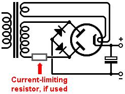
Think of the gz34 as two diodes in parallel. You can use 2 to make a bridge rectifier if you want. 170v is about half of what most power tubes in guitar circuits use.

Also make sure your reservoir (first) filter capacitor is around 22uf if you're using the tube rectifier. Larger capacitances right after tube diodes are stressful for the tube.

2k ohms. If it has 4,8,16 ohm output taps you can derive 3.8k or so using the 16 ohm tap for an 8 ohm load
Search for impedance matching or reflected impedance on transformers. If your tubes expect 3500 ohms of plate resistance (see data sheet), and your transformer is 3500 primary with a 16, 8, and 4 ohm secondary, you are fine. Hooking up a 16ohm speaker to the 16 ohm tap will give you 3500 ohms on the primary, which is exactly what the tubes in the example (pair of el34s) need.

What you can do is hook up a 16 ohm speaker on the 8 ohm tap and get 7000ohms on the primary.

This is how you can use the same output transformer for multiple tube types. This is the 6L6 Datasheet, see under fixed bias with screens at 350v, the tubes expect 6600 ohms of plate resistance. 7000ohms on your transformer primary is fine, as you can underload the tube by using too much (higher number) resistance on the primary. So yes, you can get an EL34 transformer, use it like normal with EL34s, or switch to 6L6s and use the 8 ohm tap with a 16 ohm speaker. 6l6 datasheet.png

Your 6v6s run at 8000 ohms of plate resistance at 250v, so they might not be the most interchangeable tube with EL34s. You would pull more current than the tube is spec'd for even with dropping the impedance on the output selector like the above example, as it is seeing 7k instead of 8k. Probably not the end of the world if you're not cranking it all the time. 6L6 is a closer match as it's a 30 watt tube (GC version) that runs at more normal EL34 voltages (350ish +).
 
Last edited:
What you can do is hook up a 16 ohm speaker on the 8 ohm tap and get 7000ohms on the primary.
I’m aware of your excellent info. Op said it’s a 100w transformer. I was assuming an output transformer. Maybe I have this backwards with a power transformer I haven’t read all the post. A 100w output transformer would be 4 output tubes used el34 or 6L6 usually and be around 1700 ohms. It sounded like op is building a jtm45 using 2 output tubes which require 3.4 to 4k primary for 6l6 and 7 to 8k for two 6v6. The 100 watt output transformer at 1700 ohms at 8 ohms and 3.5k at 16 0hm tap to 8 ohm wok is to low of an impedance when running only 2 6v6s. But as I say the 100 watt transformer I assumed to be an output transformer.
 
Oh I quoted your post and was talking to OP in my mind, sorry for the confusion

Good point I missed the 100w part which would imply that it probably wouldn't work for 6v6s and el34s.
 
The 100W transformer is only temporary and the other txf I’ve ordered will hopefully arrive with 6.6k and 8k primary’s.
I’ve also ordered two 6V6S tubes which will
Hopefully work!?
If not I will have to cancel that order and get some 6L6 or some KT66!!
Also the modulus JTM45 transformer says that their output transformer doesn’t work well with the el34, this must be because it’s only rated at 30W?
 
The problem I’ve got with this 170 0 170 transformer is if I want to use the 6P63 tubes I can’t easily get to 330v being the first node after rectification but I can get to 436v or there abouts with 2 diodes or GZ34.
So I think I’m just going to have to just rethink using the 6P63 and go with using the EL34 for another version.
By my probably very wrong calculations to use the 6P3P tubes and have GZ34 I would need mains txf to be 2 x 135vac CT?
 
By my probably very wrong calculations to use the 6P3P tubes and have GZ34 I would need mains txf to be 2 x 135vac CT?
To get 330Vdc you would need approximately 240Vac.
So either 240-0-240V, or a single 240V winding using a bridge rectifier. Both give the same result.

bridge3.jpg
 
I’ve put in a pair of EL34 to try and my B+ is 445v at node 1
At the next node it is 444v, then at the 82k/100k node it’s 354v the at the 3 x 100k node it’s 306v
Plate volts is 446v so I’m looking to get bout 39ma
Left EL34 gets 27ma right gets 20ma on low setting
On hi setting left is 30ma and right is 24ma

If I try and alter the bias they just get more away from each other so I think I will try and do the dual bias and hopefully be able to dial in correct bias
 
Somethings not right here?
I've lost track of what you've actually built. If you're using a bridge rectifier for B+ instead of the original two-diode rectifier, then the original bias supply won't work. You would need a cap-coupled bias supply.
 
Last edited:
hi, it looks like to me your schematic is not the same as Merlin's. To accomplish the dual bias along what you have (I think) you'd need another 15k (not sure what the correct value would be) and split the C- to a "Y" so the two side are more isolated. When you connect the dotted line it looks like you'd be lowering the C- (because you're paralleling the Rs to both sides to ground, lowering max. C- and thus increasing plate voltage). (hope that's right, 😅lol)
 
honestly not sure but (the basic idea is) each side needs to not interact so you can bias the tubes separately (which doesn't appear to be the case with the one you've drawn). Probably safer just to do Merlin's. (But maybe it could use some sort of safety in case the wiper goes intermittent or open.)
 
Then your bias voltage supply is low and your resistor divider is lowering the voltage excessively. Adjust the divider to raise negative bias

The bias on one tube effects the current load especially when you have excessive current and will need repeat adjustments back and forth until even. Your dropping or increase your b+ voltage depending on your current draw in other words.
 
Back
Top