JTM45 Build with 6P3P output tubes and GZ34

GroupDIY Audio Forum

Help Support GroupDIY Audio Forum:

This site may earn a commission from merchant affiliate links, including eBay, Amazon, and others.
I’ve checked the Ceriatone layout and it only has a 12k (which is the first 10k) then a 10k on the B+ not the third 10k?
And something else to consider is my choke is only 3H rather than 7H or I’ve seen 20H on another schematic?

Also the 0.01uf on rectifier and 0.047uf cap on fuse are not there!!?
 
Last edited:
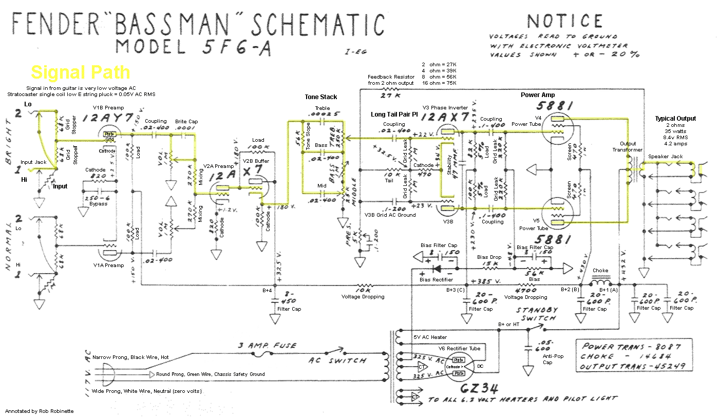
I don't think there is anything wrong with adding another de-coupling stage, but JTM45 has one less filtering stage than later amps. It's a copy of Fender 5F6-A Bassman (showing the same four stages) :

https://robrobinette.com/images/Guitar/Bassman/5F6A_Annotated_Fender_Schematic.gif

5F6A_Annotated_Fender_Schematic.gif


I've also played with that basic circuit with the four filtering stages but with later split cathodes, etc., and I don't recall any obvious motorboating sort of problems.
 
Ah yes I haven’t done the gnd connections correctly on the bias trimmers!! Oops!!View attachment 136341
how does this look?
I may be late to the party BUT:
You need a ground on the center tap of the hv winding on the PT. It's missing in the diagram but not in your amp.

Also, the source of your motorboating could be from using the same value coupling cap and resistors in the front end. You have the same time constant for the RC decoupling, 10K/16mfd, for 2 stages. That fcreates too much phase shift. I'd hang a 100mfd decoupling cap after the last B+ resistor to ground.

I redid an Ampeg B15 and used HV diodes and some a large PS cap, at least 200mfd, for power to the output stage and let the 5u4 or in your case the GZ 34 power everything else. You'll get more punch out of it and GZ 34 will never die.

HF squeal could also come from wire placement.
 
ok, some lovely ideas here which i will definetly try and see how they sound.
Ive now found the JTM50 and can see also where i can alter mine to it
the 2 x 270k resisitors are changed to 2 x 470k on the JTM50? be nice to know what this does?
it uses 5 x 32uf/500v which i got some on order, less noise? hum?
where ive got a 1k 5W into the 470R 5W pin 4 of the output tubes (EL34) the JTM50 has only 1k 5W on pin 4, dont know what difference this will make?
has 8.2k, 10k, 10k on B+ so thats the extra stage, will this improve noise/hum?
the tone stack bus bar doesnt seem to goto ground on the ceriatone layout? i was assuming it would goto the star gnd?
what difference will having the 0.01uf / 3kv and the 0.047uf /1kv? can i leave these of or are they really important?

sorry for so many questions but im really enjoying this build and it would be nice to know whats good and whats bad!!!
 
I can see my mistake with the bias now the 50k trim needs to be before the 56k resistor and yes the HV ct needs to goto gnd, I’ll use a slightly different schematic and post back up once I’ve updated.
Also looking at the tube town build the lead dress is fairly different so I’ll copy that, as I have come into tubes for the heaters from above rather than coming in from the back of the chassis.
 
the 2 x 270k resisitors are changed to 2 x 470k on the JTM50? be nice to know what this does?
Not much difference really, a slight change in the pot loading (taper).
where ive got a 1k 5W into the 470R 5W pin 4 of the output tubes (EL34) the JTM50 has only 1k 5W on pin 4, dont know what difference this will make?
Again, not much difference either way.
has 8.2k, 10k, 10k on B+ so thats the extra stage, will this improve noise/hum?
I certainly won't hurt
the tone stack bus bar doesnt seem to goto ground on the ceriatone layout? i was assuming it would goto the star gnd?
It should go to the star. Probably a drawing error.
what difference will having the 0.01uf / 3kv and the 0.047uf /1kv? can i leave these of or are they really important?
You can leave them out

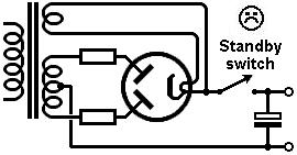
Do NOT copy the ceriatone JTM45 standby switch wiring, it will kill your rectifier. The JTM50 layout is better.
 
From an audible perspective

Id love to hear what you wish to achieve and how it ended up sounding

Its an old story that Marshall copied the Bassman - but they sound nothing alike
Main dif is that the Fender clip in the lower Hz - Marshall clip more in the higher Hz.
What is the reason for this - a filter on the Feed?
 
Yes I’ve made quite a few YouTube videos so far and it is sounding good but I do want to bring hum and noise to a minimum and also try and prove that some layouts are better than others.
My hit list so far of what I’m going to change.
1. 500ma fuse move to HV CT.
2. Tone Stack bus bar gnd to star gnd
3. Change lead dress and use screened leads where necessary
4. Check input jack wiring is correct
5. Install 5 x 32uf 500v caps
6. Install another 10k 2W stage
7. Connect and install fx loop
8. Connect PPIMV
9. V1B cap switch
10. Bright switch 3 way
11. Test and record all voltages
 
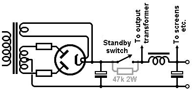
So if I’ve read it right on a few different schematics there is a 2W resistor (47k or 100k) across the standby switch and the fuse 0.5A is moved to the CT of the HV winding?
In the ceriatone JTM45 layout the switch is between the recto and the first cap, which is how you saturate and kill a normal tube rectifier.
standby2.jpg

The switch should come after the first cap, which it does in the JTM50 layout. Fuse and resistor are up to you.
standby3.jpg
 
Main dif is that the Fender clip in the lower Hz - Marshall clip more in the higher Hz.
What is the reason for this - a filter on the Feed?
Fenders used big bypass caps on the cathodes, so more bass passed through the circuit. Coupling caps from the phase inverter to the output tubes are .1uf instead of the .022uf in the Marshalls. Bigger signal caps means more bass, which distorts first and gives Fenders their signature flub in the low end.

Tone stacks are different values, too. The Fender tone stack introduces a phase shift in the treble frequencies, which is part of the reason for the classic Fender sparkle in the high end. There's an article on the internet somewhere about it, maybe buried somewhere on the rob robinette site.

https://robrobinette.com/The_Trainwreck_Pages.htm
So cool - thanks
 
Back
Top