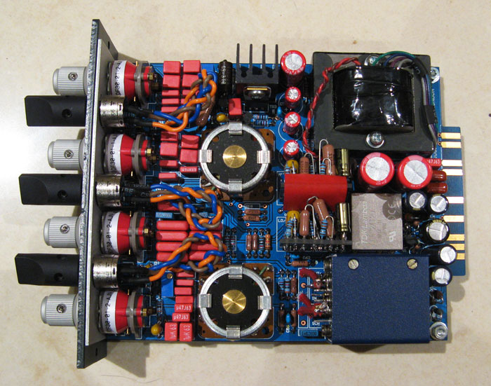
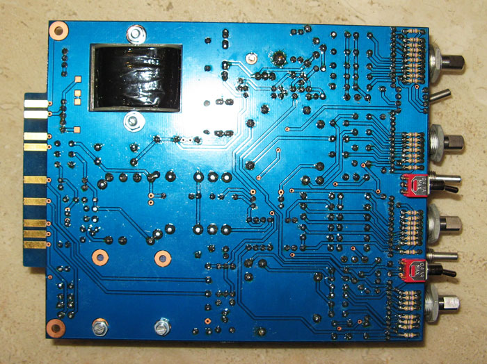
Thanks for the thread! This makes me want to build a pair or 4!
You are using an out of date browser. It may not display this or other websites correctly.
You should upgrade or use an alternative browser.
You should upgrade or use an alternative browser.
Laz EQN1084 eq - journey
- Thread starter canidoit
- Start date
Help Support GroupDIY Audio Forum:
This site may earn a commission from merchant affiliate
links, including eBay, Amazon, and others.
is it just the quality camera, and which one, or did you have some special lighting as well. etc. tips appreciated for phone-with-camera idiots like me.
Nothing much, just a digital camera will do, not a phone one, just a desktop light or whatever, and there you go, sometimes quality even on digital camera LCD's are not very real, when you load in computer you have a better view of them, i have a Lumix, and it's a good one in terms of quality/price, if this can help???????
funkymonksf
Well-known member
Hey all... I'm pondering and looking for knob ideas. What are you all doing for knobs and where are you getting them? Is there any manufacturer that sells red and blue knobs made of any metal. I also was wondering for those not using a 51x what electros (brand and lead spacing) are you using for C1, C2, C3, C4, and C7? I'd really appreciate any info or tips.
Brice Conrad
Brice Conrad
boji
Well-known member
Too bad. Keep us updated with your progress!Marcocet: Well, as expected my first attempt doesn't quite work...it's VERY VERY quiet.
PCB scans for mark off sheets or reference.
(Right Click link and save to download)
EQN 2009 PCB scan-normal - click here
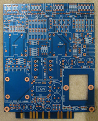
EQN 2009 PCB scan-invert - click here
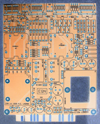
(Right Click link and save to download)
EQN 2009 PCB scan-normal - click here

EQN 2009 PCB scan-invert - click here

Sorry everyone if I have not replied, I am still trying to get my head around this build and also waiting on a second project to do, so that I can buy all the parts in one go and save on shipping.
Quick notes:
...
R29 is a resistor between 600r to 1.2kohm. In Petes BOM "TDB" means "To be determined". Its not a part :
1 builder used 1K for R29 but was getting 1db gain loss when they're inline, both while engaged and bypassed so Pete recommended 750r for R29.
RV4 & RV5 are little blue trimmers.
If you are not getting enough gain from your unit with RV4 adjusted, then you must lower the value of R29 to increase the gain in the output amp.
"I can help you out on the trimmer adjustment, the rv4 is the gain trimmer, it is in-between the EQ section and the output amp. RV5 is to adjust the output stage, so that the distortion is symmetrical, you need a scoop to adjust this properly, check the ez1290 build from Madriaanse, in his build pdf is a explanation how to "
"
- DJN
RV4 & RV5 - the alignment procedure for these trimmers is similar to the 'symmectrical clipping' process on the 1290 preamp. (I think you need an oscillator to do this??)
...
Corrected on BOM Exel - Petes BOM 1MH meant to be 1mH
66 - on BOM Exel RF Inductors 1000uH (1mH) 130mA 14ohms
RF Inductors 1000uH 130mA 14ohms = http://au.mouser.com/ProductDetail/EPCOS/B78108S1105J/?qs=v4Mlc8l4PHm9xnPqu6pYww%3d%3d
(referred to as choke)
...
Grayhill switch pin:
If you loose the pin for your Grayhill switch, use the leg of a resistor and cut to size.
...
The replacement screws for the input transformer are a little too long and need to be shortened which sometimes damages the threading.
...
71 - 1N400X series, 1N4001 will do
Rectifiers Vr/50V Io/1A T/R
http://au.mouser.com/ProductDetail/Fairchild-Semiconductor/1N4001/?qs=sGAEpiMZZMutXGli8Ay4kJFypYesfd9y2GUYLufLOL0%3d
...
80 - DC-1 TDK LAMBDA CC6-2412DF-E
CONV DC/DC 6W DUAL 24V +-12V PCB
http://parts.digikey.com/1/parts/733027-conv-dc-dc-6w-dual-24v-12v-pcb-cc6-2412df-e.html
...
27 - 4M7 miniature
Carbon Film Resistors - Through Hole 4.7M OHM 5% 1/4W
Dimensions: 1.7 mm Dia. x 3.2 mm L
http://au.mouser.com/ProductDetail/KOA-Speer/CFS1-4CT52R475J/?qs=sGAEpiMZZMu61qfTUdNhG1dhquwH4o0F6GnhHghqdcU%3d
...
RV1, RV2, RV3 linear small format pots should be the PRV6/PARV6 kind of size with center detent
...
Excel BOM version 1.4 update.
Quick notes:
...
R29 is a resistor between 600r to 1.2kohm. In Petes BOM "TDB" means "To be determined". Its not a part :
1 builder used 1K for R29 but was getting 1db gain loss when they're inline, both while engaged and bypassed so Pete recommended 750r for R29.
RV4 & RV5 are little blue trimmers.
If you are not getting enough gain from your unit with RV4 adjusted, then you must lower the value of R29 to increase the gain in the output amp.
"I can help you out on the trimmer adjustment, the rv4 is the gain trimmer, it is in-between the EQ section and the output amp. RV5 is to adjust the output stage, so that the distortion is symmetrical, you need a scoop to adjust this properly, check the ez1290 build from Madriaanse, in his build pdf is a explanation how to
- DJN
RV4 & RV5 - the alignment procedure for these trimmers is similar to the 'symmectrical clipping' process on the 1290 preamp. (I think you need an oscillator to do this??)
...
Corrected on BOM Exel - Petes BOM 1MH meant to be 1mH
66 - on BOM Exel RF Inductors 1000uH (1mH) 130mA 14ohms
RF Inductors 1000uH 130mA 14ohms = http://au.mouser.com/ProductDetail/EPCOS/B78108S1105J/?qs=v4Mlc8l4PHm9xnPqu6pYww%3d%3d
(referred to as choke)
...
Grayhill switch pin:
If you loose the pin for your Grayhill switch, use the leg of a resistor and cut to size.
...
The replacement screws for the input transformer are a little too long and need to be shortened which sometimes damages the threading.
...
71 - 1N400X series, 1N4001 will do
Rectifiers Vr/50V Io/1A T/R
http://au.mouser.com/ProductDetail/Fairchild-Semiconductor/1N4001/?qs=sGAEpiMZZMutXGli8Ay4kJFypYesfd9y2GUYLufLOL0%3d
...
80 - DC-1 TDK LAMBDA CC6-2412DF-E
CONV DC/DC 6W DUAL 24V +-12V PCB
http://parts.digikey.com/1/parts/733027-conv-dc-dc-6w-dual-24v-12v-pcb-cc6-2412df-e.html
...
27 - 4M7 miniature
Carbon Film Resistors - Through Hole 4.7M OHM 5% 1/4W
Dimensions: 1.7 mm Dia. x 3.2 mm L
http://au.mouser.com/ProductDetail/KOA-Speer/CFS1-4CT52R475J/?qs=sGAEpiMZZMu61qfTUdNhG1dhquwH4o0F6GnhHghqdcU%3d
...
RV1, RV2, RV3 linear small format pots should be the PRV6/PARV6 kind of size with center detent
...
Excel BOM version 1.4 update.
funkymonksf
Well-known member
Would anyone with the 1084 faceplate be willing to measure the diameter of the switch/ knob markings? I am trying to order knobs for my kit (which has yet to arrive). Just want to make sure they small/ big enough in diameter to not cover any of the dots or markings.
Thanks any how,
Brice Conrad
Thanks any how,
Brice Conrad
peter purpose
Well-known member
I wouldn't go any bigger than 0.74" / 18.8mm for the bigguns... 0.45" / 11.4mm for the small.
funkymonksf
Well-known member
Thanks Peter
I have finally got around to ordering the parts from Mouser and Digikey. I am very excited! ;D
I have placed a word version of the parts I ordered on the first post of this thread if anyone wants to download it for guidance. The hyperlinks on the word document are active so you can see what I have ordered except for the Digikey list section which you will have to cut and paste into the Digikey website.
Please inform me if you notice something wrong with it so that I may be able to correct it.
Hopefully someone will find this list useful. Thanks to the other posters who placed their list or parts up which has helped me to verify some of the components I have chosen. I went for lower tolerances on most of my components like 1% than 5% for the resistors and chose mid price components than the cheapest.
I am actually glad that it took me this long, because the first time I was gathering my BOM list, some were not available, now all the parts are available for a hopefully smooth journey : ))
Regarding the knobs I used for my build, I was very much impressed by Mako's EQN reasoning behind his knob selection - webpage http://mnats.net/pp-eqn_notes.html (recommended reading because he identifies some alternative build process and provides useful build instructions). His recommendation of parts was also taken into consideration when I built my list and I have actually used some of his selection and also Kato, so thanks guys.
So if you refer to both my Word ordered parts list and the Excel BOM list, you should have a list of all the components I used in this build which I hope is complete and correct. Only time will tell...
Sawed off the 51x tab since my main use for this build would be for the API lunchbox (16 volts).
I first considered making this swappable with the 51x rack by keeping the 51x tab on but I had already spent money on the DC-DC converters and parts and did not plan to go 51x, so I decided it wouldn't be worth it for my purpose.
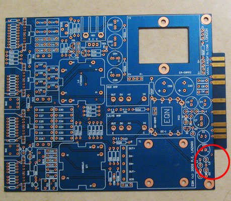
Be careful if you decide to saw this tab off. Be sure to have the board secured well because I felt that with the swinging motion and sometimes the saw gets jammed that there may be a possibility that you snap the board while sawing it.
I first considered making this swappable with the 51x rack by keeping the 51x tab on but I had already spent money on the DC-DC converters and parts and did not plan to go 51x, so I decided it wouldn't be worth it for my purpose.

Be careful if you decide to saw this tab off. Be sure to have the board secured well because I felt that with the swinging motion and sometimes the saw gets jammed that there may be a possibility that you snap the board while sawing it.
opAmps
Took me almost 2 days to do these little opAmps. I may have to trim the pins length, I will find out I guess once I solder the sockets on the main PCB.
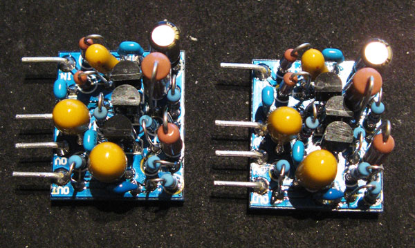
I used BC184C transistors that had a HFE of over 600.
I made sure that all components did not touch each other at all even though they were so close together. You may have to do some component angling to ensure space between components.
I used the pins supplied in Pete's kit for the pins for the opAmps so that it can be connected to the PCB board.
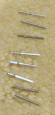
I soldered all the other parts first before soldering the pins. I slightly bent the pin before soldering the pin for those tight areas. Then I bent the pin into shape after.
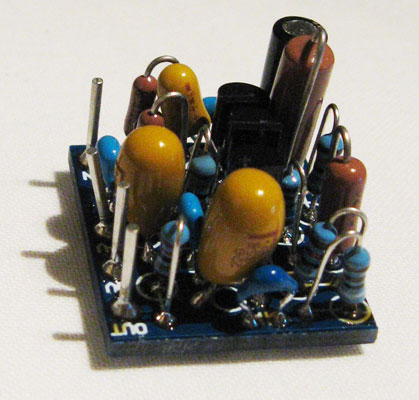
I was very careful when bending the pins after soldering because it is close to the edge of the board and may weaken the board or snap it.
I think the key is to firmly hold the little board and bend the pins very slowly with a long nose pliers.
Took me almost 2 days to do these little opAmps. I may have to trim the pins length, I will find out I guess once I solder the sockets on the main PCB.

I used BC184C transistors that had a HFE of over 600.
I made sure that all components did not touch each other at all even though they were so close together. You may have to do some component angling to ensure space between components.
I used the pins supplied in Pete's kit for the pins for the opAmps so that it can be connected to the PCB board.

I soldered all the other parts first before soldering the pins. I slightly bent the pin before soldering the pin for those tight areas. Then I bent the pin into shape after.

I was very careful when bending the pins after soldering because it is close to the edge of the board and may weaken the board or snap it.
I think the key is to firmly hold the little board and bend the pins very slowly with a long nose pliers.
Component selection
Be careful on component selection for the following areas. My store BOM reflect the following result so I would advise to change the parts ordered for these following areas for a smaller component equivalent.
There is a resistor on the opAmps that need to be smaller in length so that it doesn't stand too high when mounted. As you can see, I had to angle the tall resistor and also angle the way the top opAmp sits.
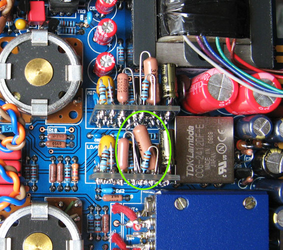
This area here needs to have smaller component dimensions so that they sit in nicely.
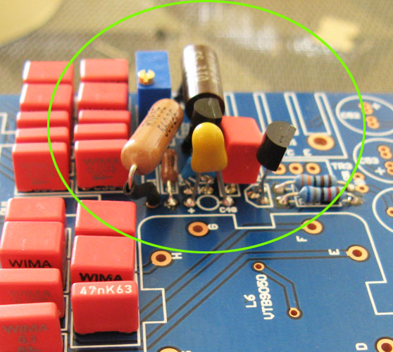
Be careful on component selection for the following areas. My store BOM reflect the following result so I would advise to change the parts ordered for these following areas for a smaller component equivalent.
There is a resistor on the opAmps that need to be smaller in length so that it doesn't stand too high when mounted. As you can see, I had to angle the tall resistor and also angle the way the top opAmp sits.

This area here needs to have smaller component dimensions so that they sit in nicely.

VTB9046 transformer
I used a nut and washer to allow the bolt supplied with the EQN kit to fit with mounting the VTB9046 transformer to the board. An alternative method instead of cutting the bolt shorter to fit. The nut I used as a spacer was slightly bigger (3M I think) than the EQN bolt which allowed it to just slide down the bolt into position but not too big that it would slip right through the bolt head.
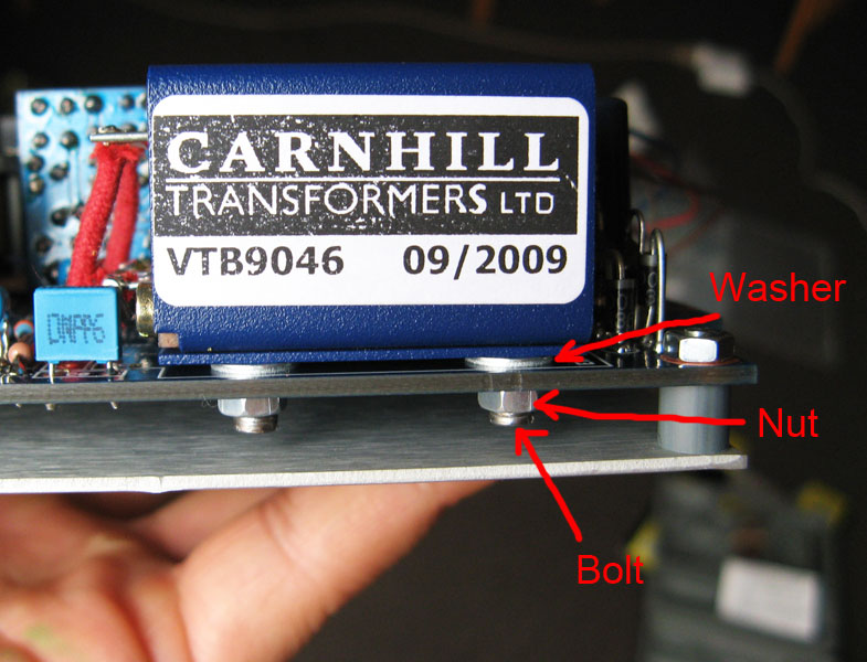
I used a nut and washer to allow the bolt supplied with the EQN kit to fit with mounting the VTB9046 transformer to the board. An alternative method instead of cutting the bolt shorter to fit. The nut I used as a spacer was slightly bigger (3M I think) than the EQN bolt which allowed it to just slide down the bolt into position but not too big that it would slip right through the bolt head.

Pot wiring
Soldering the pot wiring to the board circled in green on the pic can get a little tricky once all the components are in place. I should have soldered three loose wires into place first here before soldering the components around it. Then solder the pot to the loose wires last.
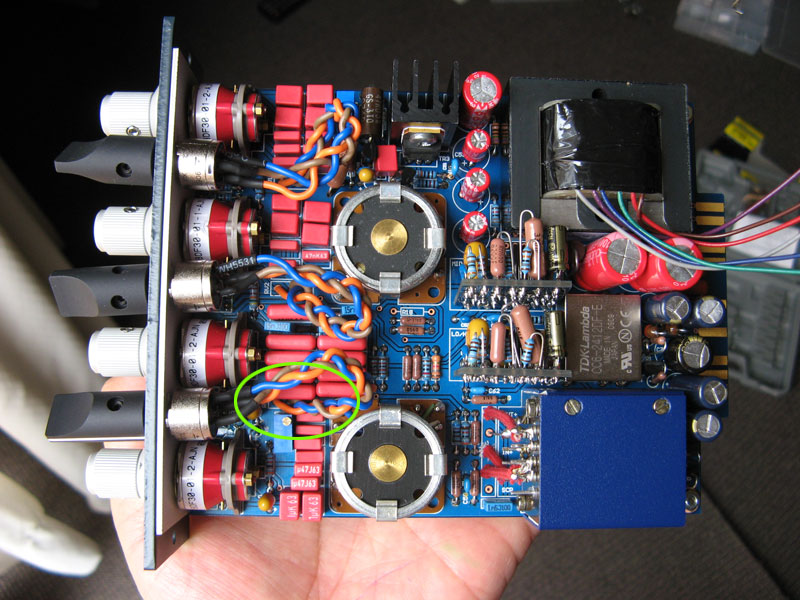
Soldering the pot wiring to the board circled in green on the pic can get a little tricky once all the components are in place. I should have soldered three loose wires into place first here before soldering the components around it. Then solder the pot to the loose wires last.

Pins for grayhill switches
Thanks to JBVries. What a valuable pic and instruction!
Thanks to JBVries. What a valuable pic and instruction!
JBVries said:Just to make things a little easier on future builders. Make sure you have the flat part of the shaft opposite position 2 and drop pins in these locations....
12 and 6
12 and 8
12 and 5
12 and 5
Left to right...
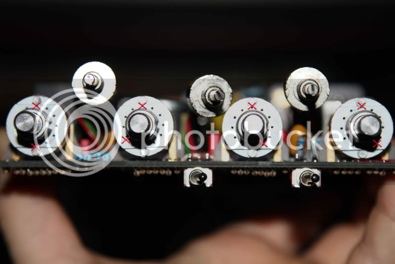
If this is incorrect please give a shout so I can take this down but I'm pretty sure it's right.
Calibration RV5 - Symetrical Clipping
##Note: Things to watch out for to ensure a trouble free calibration
From my understanding of this process is that, you are trying to get a sine wave to distort inside the EQN. You are not to feed it a distorted sine wave but a sine wave that becomes distorted inside the EQN because it is being fed the signal too hot into the EQN.
The EQN requires a high sine wave signal in order for the sine wave to clip on the Oscilloscope in the RV5 callibration process.
This took me a while to get but I think what I have done is correct.
I installed my EQN on it's own in my lunchbox on the far left, so that I can have access to the RV4 and RV5 trimpots
I used my Macbook Pro as the signal generator, using Logic software that can produce a 1Khz sine wave
I connected the Macbook Pro out to a Great River preamp to boost the signal
I connected the Great River preamp out to the input of the EQN through the lunchbox
I connected the probe of my Oscilloscope to Pin 2 of the EQN output through the lunchbox
I connected the ground cable of my probe to Pin 1 of the EQN output through the lunchbox
I set my EQN as follows: EQ in, ALL frequencies set to OFF, Gain knob to 0
I turned the RV4 Counterclockwise to as far as it can go, so that the output stage is fed the incoming signal in the EQN as high as possible to help cause the sine wave to clip on the Oscilloscope
In Logic, I set the sine wave level to Max(in the red)
The GR input leds shows red
I turned the output knob of the GR so that the output led of the GR is red
I ended up with this reading on my Oscilloscope, where the clipping is on the bottom
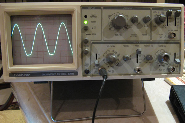
The problem with this, is that if I turn RV5, to try to get both clipping top and bottom, it actually makes the bottom clipping wider than the top. I have realised in order to get a symetrical clipping, I have to get my initial clipping to start at the top, and not the bottom. I have noticed that the bottom clipping increases at a larger rate than the top clipping hence, the funny shape sine I got.
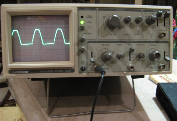
In this situation, since the clipping was at the bottom. I turned RV5 counterclockwise, which slowly rounded the bottom clipping into a smooth sine again.
I decided to boost the signal by pressing the impedence button on my GR and then boosted the GR output knob more until this time, I got a top clipping.
I turned RV5 clockwise until the bottom of the sine wave started to clip and I stopped turning RV5 until I got a similar size bottom clipping to the top
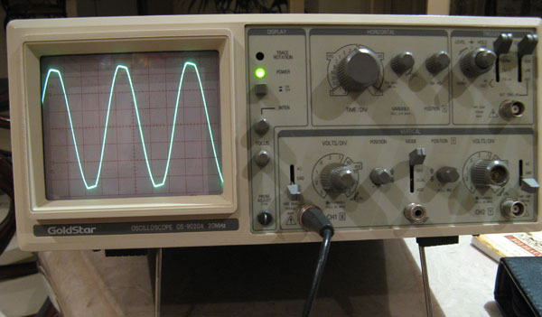
I tested my EQN after using this method of calibration and so far so good. The unit sounds pretty good!!!
##Note: Things to watch out for to ensure a trouble free calibration
- Make sure to connect the signal generator to the EQN solidly
- Use a preamp to get a signal high enough into the EQN
From my understanding of this process is that, you are trying to get a sine wave to distort inside the EQN. You are not to feed it a distorted sine wave but a sine wave that becomes distorted inside the EQN because it is being fed the signal too hot into the EQN.
The EQN requires a high sine wave signal in order for the sine wave to clip on the Oscilloscope in the RV5 callibration process.
This took me a while to get but I think what I have done is correct.
I installed my EQN on it's own in my lunchbox on the far left, so that I can have access to the RV4 and RV5 trimpots
I used my Macbook Pro as the signal generator, using Logic software that can produce a 1Khz sine wave
I connected the Macbook Pro out to a Great River preamp to boost the signal
I connected the Great River preamp out to the input of the EQN through the lunchbox
I connected the probe of my Oscilloscope to Pin 2 of the EQN output through the lunchbox
I connected the ground cable of my probe to Pin 1 of the EQN output through the lunchbox
I set my EQN as follows: EQ in, ALL frequencies set to OFF, Gain knob to 0
I turned the RV4 Counterclockwise to as far as it can go, so that the output stage is fed the incoming signal in the EQN as high as possible to help cause the sine wave to clip on the Oscilloscope
In Logic, I set the sine wave level to Max(in the red)
The GR input leds shows red
I turned the output knob of the GR so that the output led of the GR is red
I ended up with this reading on my Oscilloscope, where the clipping is on the bottom

The problem with this, is that if I turn RV5, to try to get both clipping top and bottom, it actually makes the bottom clipping wider than the top. I have realised in order to get a symetrical clipping, I have to get my initial clipping to start at the top, and not the bottom. I have noticed that the bottom clipping increases at a larger rate than the top clipping hence, the funny shape sine I got.

In this situation, since the clipping was at the bottom. I turned RV5 counterclockwise, which slowly rounded the bottom clipping into a smooth sine again.
I decided to boost the signal by pressing the impedence button on my GR and then boosted the GR output knob more until this time, I got a top clipping.
I turned RV5 clockwise until the bottom of the sine wave started to clip and I stopped turning RV5 until I got a similar size bottom clipping to the top

I tested my EQN after using this method of calibration and so far so good. The unit sounds pretty good!!!
Similar threads
- Replies
- 2
- Views
- 578


