You are using an out of date browser. It may not display this or other websites correctly.
You should upgrade or use an alternative browser.
You should upgrade or use an alternative browser.
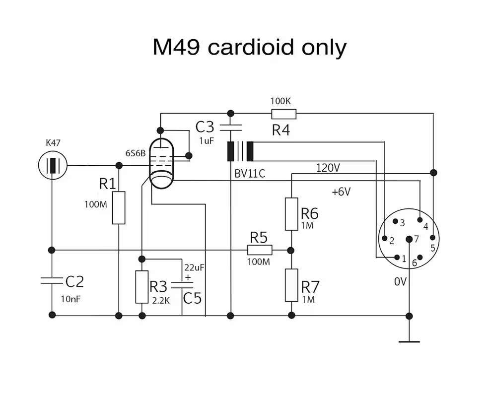
M49 Alternate schematic for cardioid only
- Thread starter elskardio
- Start date


Help Support GroupDIY Audio Forum:
This site may earn a commission from merchant affiliate
links, including eBay, Amazon, and others.

rock soderstrom
Tour de France
Yes, you can. This will work.Can I simply remove the back diaphragm polarization?
k brown
Well-known member
This may be of some help:Hi Guys,
I'm planning to build Oliver Archut's alternate M49 schematic.
I want to build the mic for cardioid only. Can I simply remove the back diaphragm polarization?
Thanks
https://repforums.prosoundweb.com/index.php?topic=33882.15
Last edited:
micaddict
Well-known member
A pure cardioid M49. Sounds nice. ") Yes, it will sound different from the cardioid setting in a multipattern mic. You may actually prefer it. S/N ratio can be a little better, too.
Yes, it will sound different from the cardioid setting in a multipattern mic. You may actually prefer it. S/N ratio can be a little better, too.
BTW, you can have both in one mic. Horch RM2J is one example; Wunder Audio CM7 G is another.
Come to think of it, wasn't there a switch (S2) even on the M49. Man, I'm really rusty.
Anyway, although I cannot help you with minute technical details, I will be following your efforts with interest. Good luck and keep us posted!
Yes, it will sound different from the cardioid setting in a multipattern mic. You may actually prefer it. S/N ratio can be a little better, too.BTW, you can have both in one mic. Horch RM2J is one example; Wunder Audio CM7 G is another.
Come to think of it, wasn't there a switch (S2) even on the M49. Man, I'm really rusty.
Anyway, although I cannot help you with minute technical details, I will be following your efforts with interest. Good luck and keep us posted!
You can put a switch to disconnect the polarization circuit (disconnect the 1000pf cap from ac701 grid) you can see it is S2 on Neumann schematics
elskardio
Well-known member
Interesting reading!
“The theory of none voltage difference at cardiode setting sounds great but the reality is that 60V (backplate) vs. 60V (back-membrane) will still push against and repell, displacing the membrane and changing overall the sound pick up.”
Sounds less than ideal…
To my understanding the polar pattern will be more hypercardioid with the back membrane disconnected. I always liked mic that are more directional. I will try to compare both configuration

“The theory of none voltage difference at cardiode setting sounds great but the reality is that 60V (backplate) vs. 60V (back-membrane) will still push against and repell, displacing the membrane and changing overall the sound pick up.”
How and why, i wonder? And push/repel against what? The rear diaphragm and the backplate?
elskardio
Well-known member
How and why, i wonder? And push/repel against what? The rear diaphragm and the backplate?

This is a quote from Oliver Archut by the way.
elskardio
Well-known member
Hi guys,
I've updated the drawing in the first post.
I'm working on a pcb for the microphone and currently planning to make 2 floating points for the capsules hi-z connections.
Any other particular details I should be aware?
cheers
I've updated the drawing in the first post.
I'm working on a pcb for the microphone and currently planning to make 2 floating points for the capsules hi-z connections.
Any other particular details I should be aware?
cheers
currently planning to make 2 floating points for the capsules hi-z connections.
Why two?
elskardio
Well-known member
Sorry but I'm not following...Why two?
rock soderstrom
Tour de France
Sorry but I'm not following...
I think Khron is telling you that you only need one high impedance floating point (isolated turret) because we are talking about impedances and that means alternating current. For AC, the capsule side of the C2 capacitor is more or less at ground potential because the capacitor is a frequency dependent resistor (or conductor). Ergo, you only have a high impedance point. Right or wrong?The tube grid is indeed a high-impedance node, but how and why is the other side of the capsule ALSO a high-impedance node?
Remember how capacitors work? They block what, and allow what to (virtually) pass through?
Last edited:
rock soderstrom
Tour de France
The more I think about my (and Khron's) explanation, the more uncertain I become, because if you look at it that way, then the grid of the tube would AC wise also be on ground potential, since the capsule is actually also a capacitor.Right or wrong?
Brainfart?
the grid of the tube would AC wise also be on ground potential
It technically sort of pretty much already is, via the grid resistor
 But not through the capsule itself, because the capsule CREATES the signal, rather than shunting it away from elsewhere.
..... Right..?
rock soderstrom
Tour de France
I'll have to think about that now, I think I'll take a hot bath, that helps! Ahoy!It technically sort of pretty much already is, via the grid resistor
..... Right..?

I think it's worth treating it as a high impedance point since the capacitor creates a frequency-dependent "pass-through" for AC. If you lower the impedance to the backplate due to some circuitboard impedance or contamination, you would also effect the frequency of the RC filtration of C2. There's a reason R5 is 100M and not just 1M.
I think it's worth treating it as a high impedance point since the capacitor creates a frequency-dependent "pass-through" for AC. If you lower the impedance to the backplate due to some circuitboard impedance or contamination, you would also effect the frequency of the RC filtration of C2. There's a reason R5 is 100M and not just 1M.
Make it 10uF then, and then you can reduce the resistor to 100k, to get the same 0.16Hz turnover frequency.
Same thing, it's a bog-standard RC filter, no voodoo-magic going on there.R5's 100Meg in order to achieve good filtering with "just" the 10nF of C5 (physically smaller and more long-lived than an electrolytic, and to not have the grid resistor as the only 100Meg on the bill-of-materials).
No disagreement there. Just saying that with the parts selection as-is, there would be no issue with making the R5/C2/Backplate junction hi-z and calling it a day.Make it 10uF then, and then you can reduce the resistor to 100k, to get the same 0.16Hz turnover frequency.
R5's 100Meg in order to achieve good filtering with "just" the 10nF of C5 (physically smaller and more long-lived than an electrolytic, and to not have the grid resistor as the only 100Meg on the bill-of-materials).
elskardio
Well-known member
Most U47 & M49 microphones I see have the backplate connected to a floating point. I figured there must be a benefit...
Similar threads
- Replies
- 237
- Views
- 9K
- Replies
- 34
- Views
- 1K