Really nice boards, and really easy project. I would recommend this project for anyone that has not done one before. I decided to Time myself, and combine it with notes:
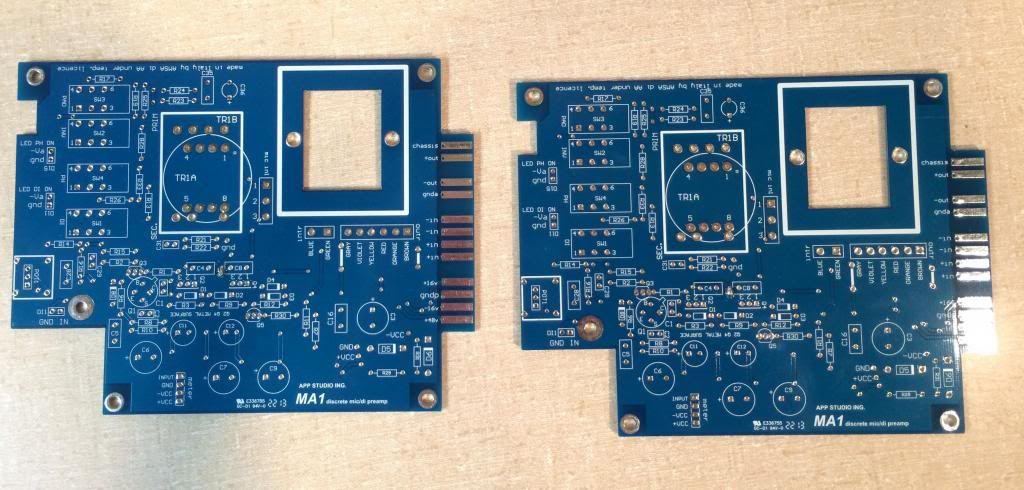
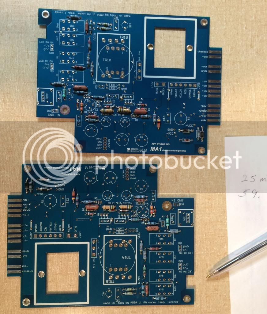
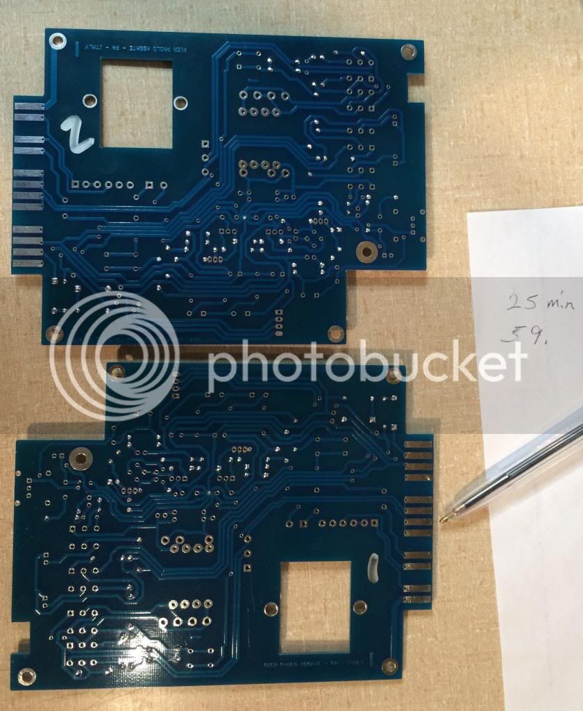
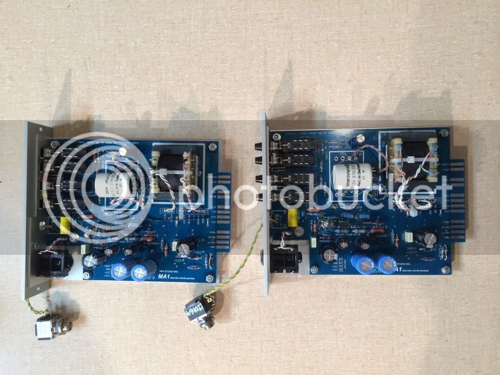
1) Always a good idea to photograph the board before starting. That way if you want to know what was there before you covered it up, you can see. My boards arrived with the ground patch mentioned earlier already done nice and clean! (thanks ppa!). In my case I am going to simultaneously do 2 boards. Boards have plenty of room for even 1/2 Watt resistors, I was able to find reasonable substitutes for every part lying around the shop. I will order the precise components where needed.
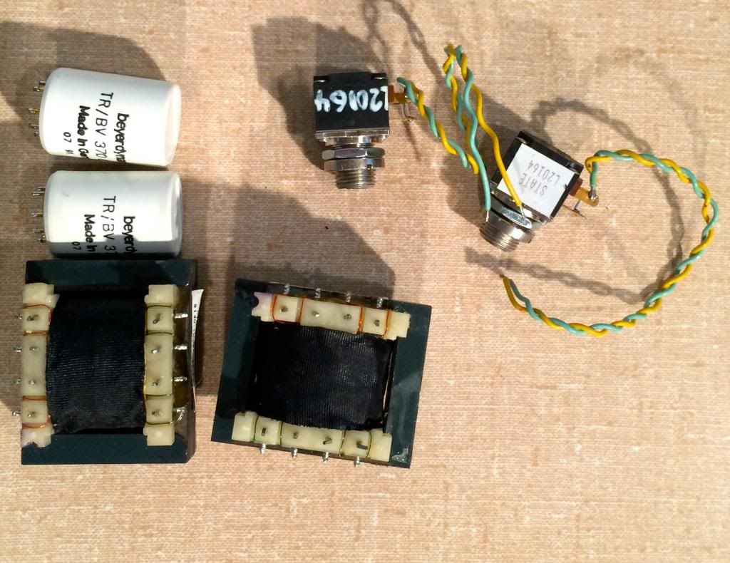
2) I have some iron that I think will work. The little Beyers are nice (1:10, triple Mu Metal shields), and the outputs are quadrafilar steel, which should add a bit of dirt to my vintage. I can always pull and replace if I need too. I want to finish this quic (test before bed), so I choose my only 25K rev log pot I have lying around, I will have to order one that fits. Except for the pots (which I got from classic api) I had everything.
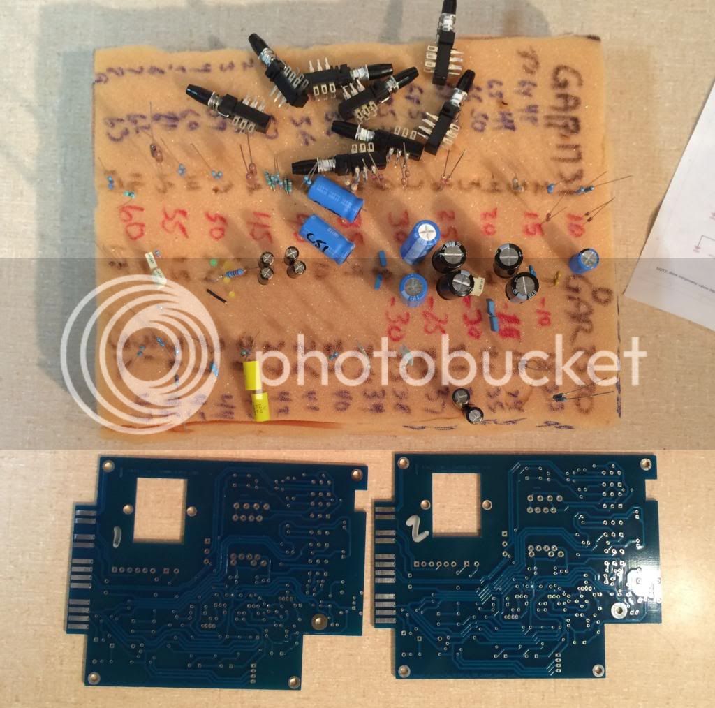
3) All resistors chosen and stuck in a numbered foam pad. I didn't measure time for the component selection part. The only matched part are the 6.8K resistors (match better than .1%). The 750 ohm resistors are marked as 1% because I assume the set the value of the PAD.
Build Note: This thing has TONS of PSU isolation. 1000uF, 100uF and little bypass cap on the TOP rail and the Ground rail. The ground rail is not connected to the audio rail. The bottom rail just does LED's I think. This presents some problems for choosing ground to isolate the transformer case, and possibly for Phantom power. More on that later.
Build note: There are inconsistencies between the BOM and the Schematic in terms of component value. The BOM is the correct source (see earlier posts).
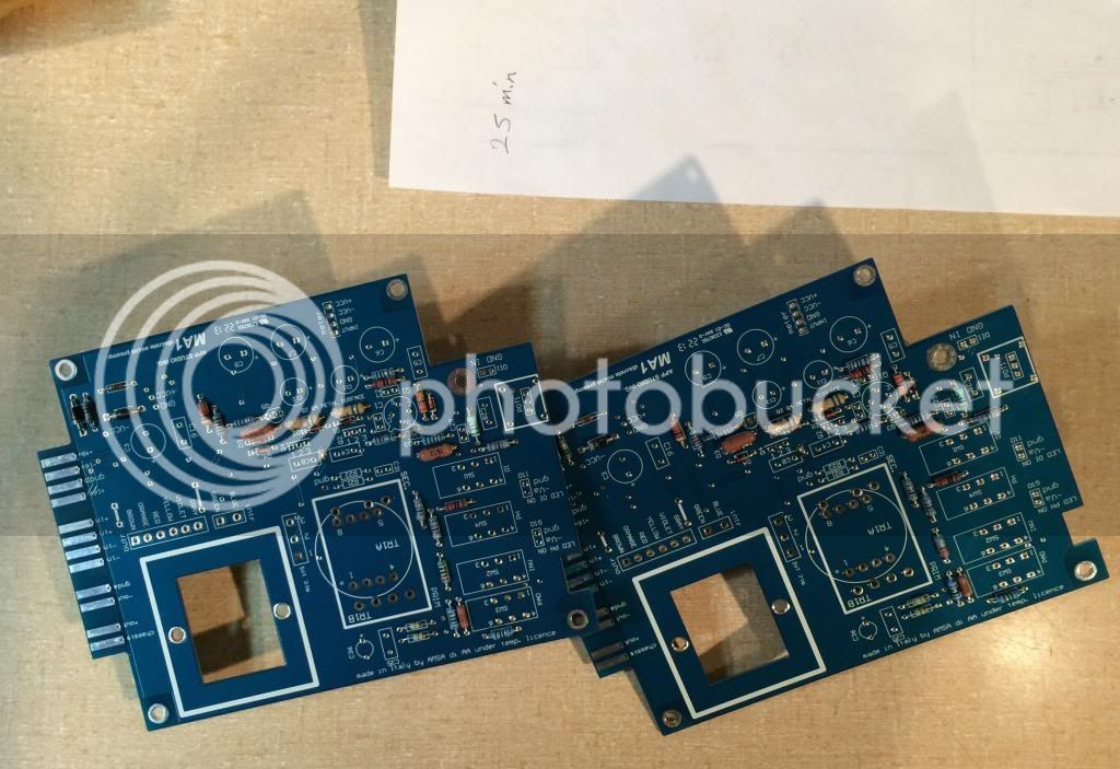
4) 25 minutes flat, to stuff the flat components on 2 boards. Easy peasy - .4" lead bends work everywhere except the 1n4148 diodes which are shorter. Pads are large, holes are well sized. Space is plentiful. Nice board for a 500 Pre.
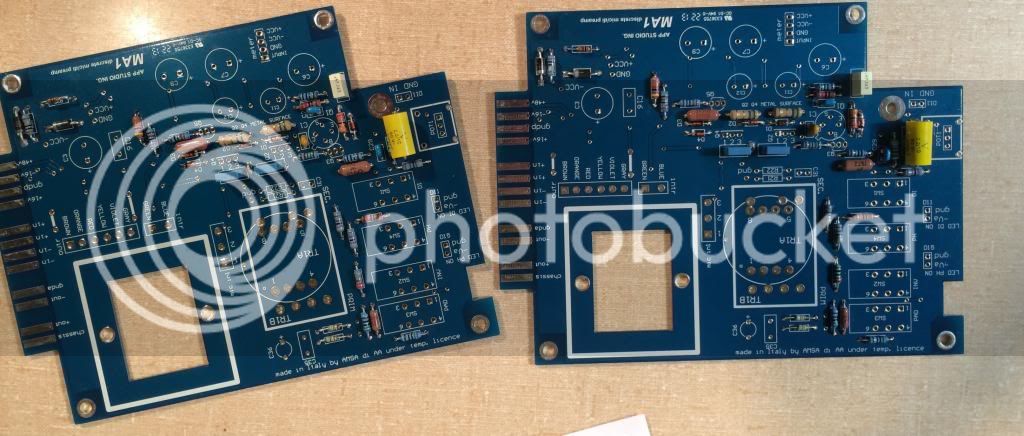
5) 59 Minutes in top soldered, clipped and bottom touched.
Looking good, but I will clean later before I put on the switches, don't like to get flux cleaner in the switches.
6) 1:21 in, Short caps and a good cleaning before I start putting stuff in that's hard to clean. I beefed up some of the film audio path bypass caps, because I had them. There are those that think these don't do anything audible, and I have no opinion on that, but I always do them if I can (sort of a wave a dead chicken manouver). I do however prefer to use non wound types when possible (layered like WIMA's) because they are potentially less inductive. One wound film cap on the DI, because I had no 1uF caps.
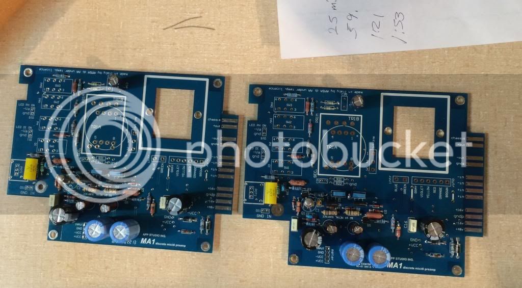
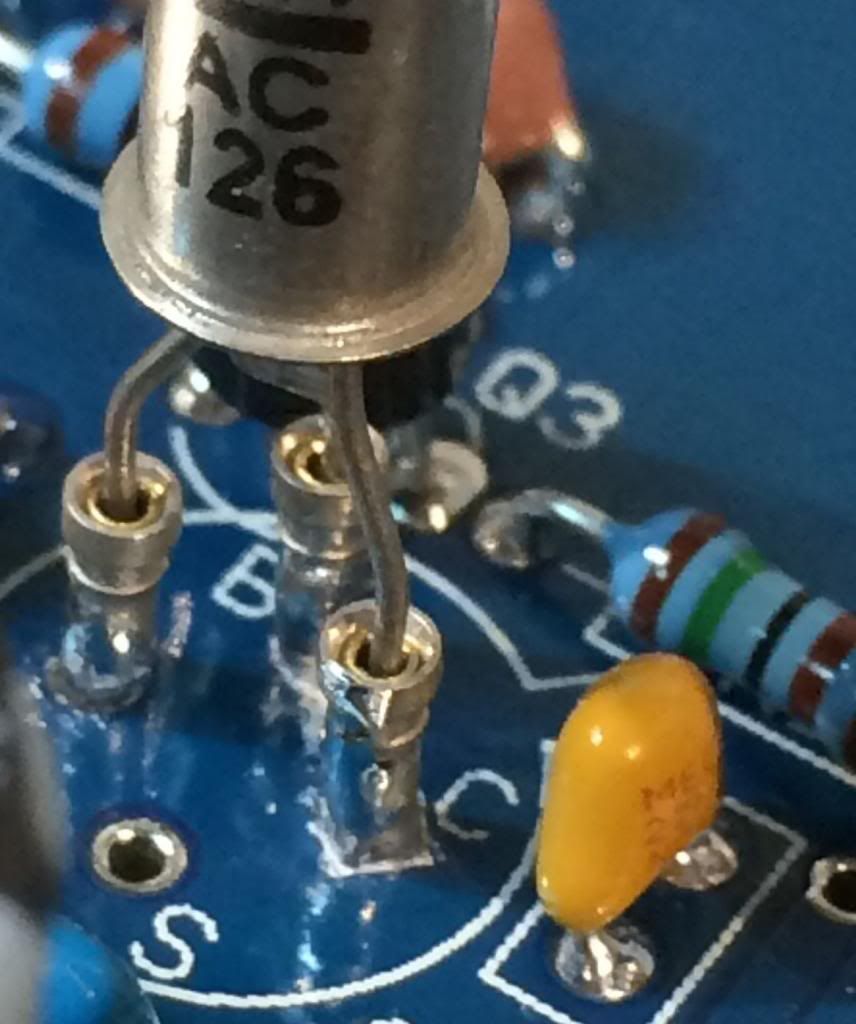
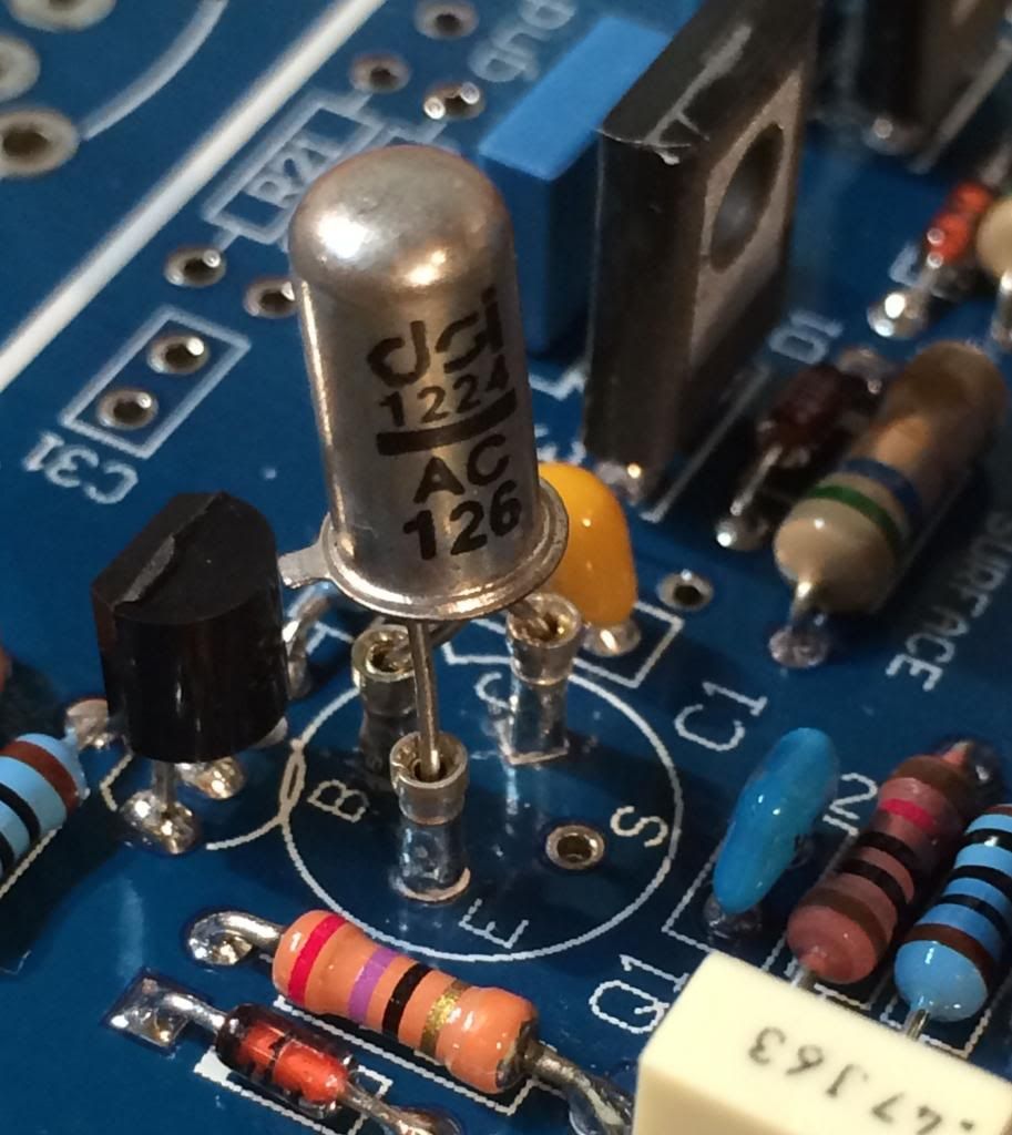
7) 1:53 in, Tall caps and silicon (and germanium!).
I put the germanium in using sockets, because the datasheets of these little fella's is sketchy (couldn't they just say "viewed from bottom" somewhere?) and I don't trust myself. However the pictures earlier in the thread are correct and help. Anyway you can see (barely) the center lead has to bend under on the AC126 to fit the board pinout. It crosses between the other two legs.
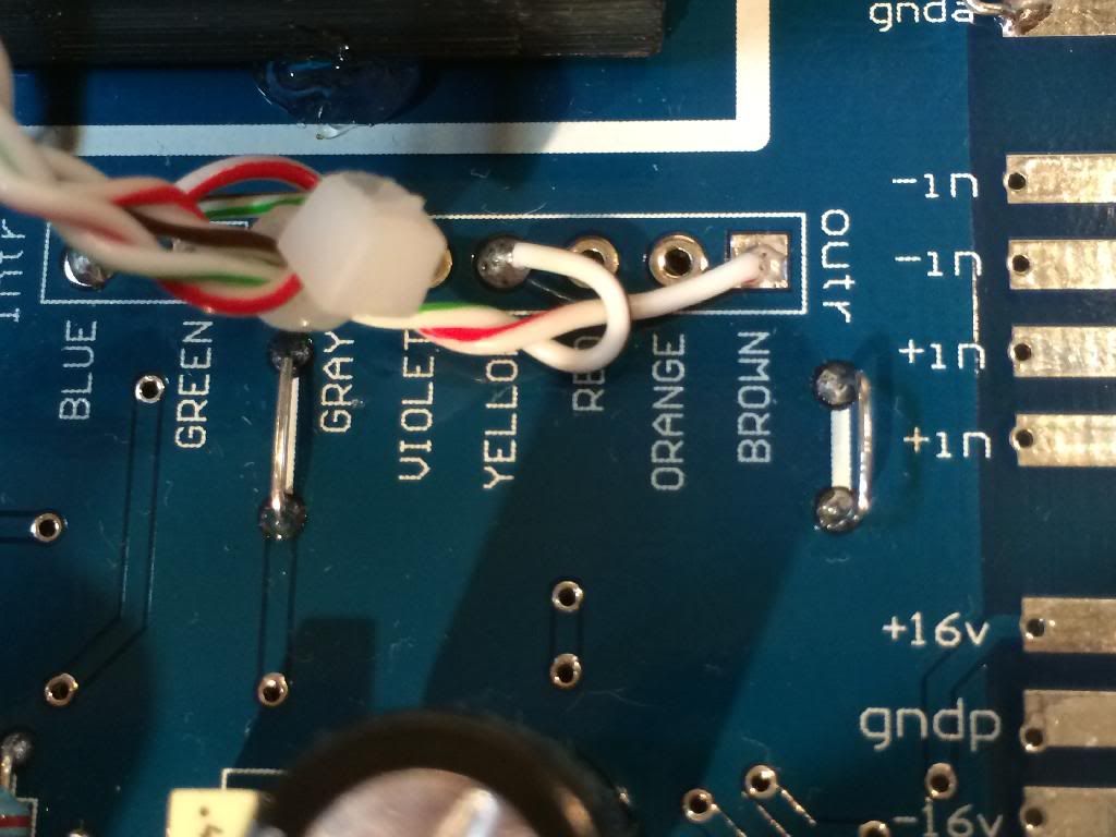
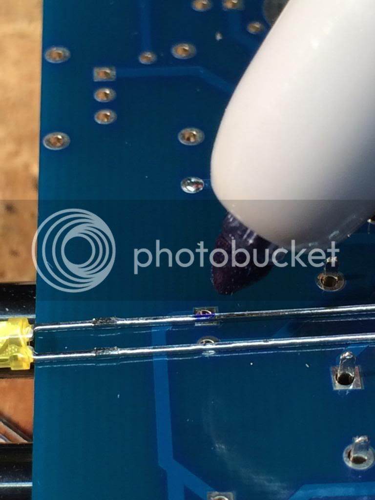
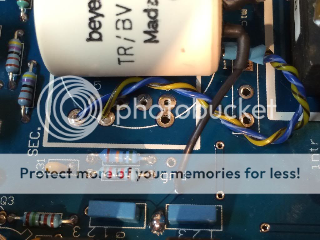
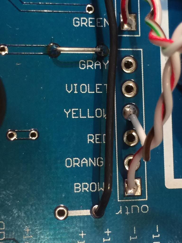
8) 2:20 in, I put switches in both, and iron in one before bed. Got it on the bench and it passed signal BUT there is a strap (marked next to the gray wire marked on the output transformer pads). That strap needs to be populated. The transformers also are supposed to be strapped for a 1:2 step up. Everything nice and cool and working though. Lights go on when I push DI and Phantom. Continued after work.
You need this strap installed, or there is no signal to the transformer.
The ground strap shown also needs to be installed. This ties the star ground to power ground. The board approaches grounding with a star ground approach. That's not how I ground my API 500 series racks instead I tie chassis to audio ground at the rack slot, and then tie chassis to power ground at the PSU. ( I was able to change the grounding approach with Pier's help with a single trace cut on the MA1. PM me if you want to ground that way, it is not needed. It will work either way).
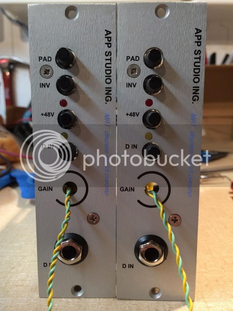
Aligning front panels.
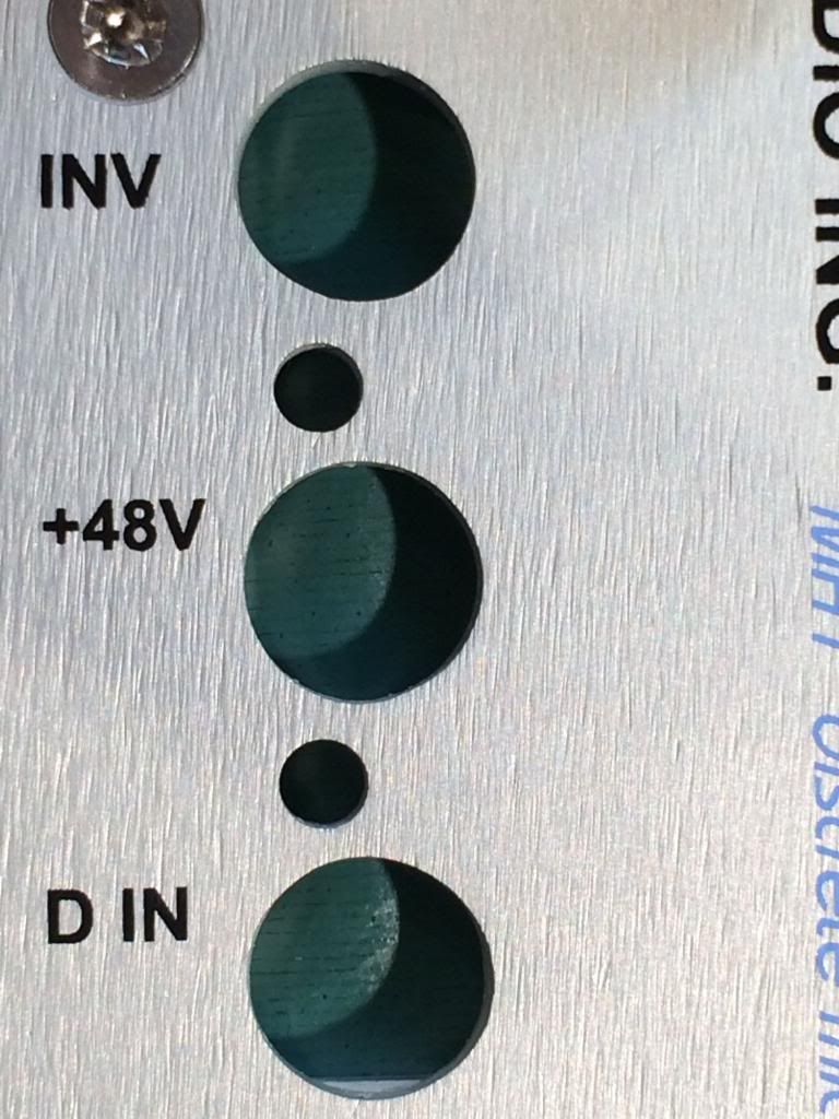
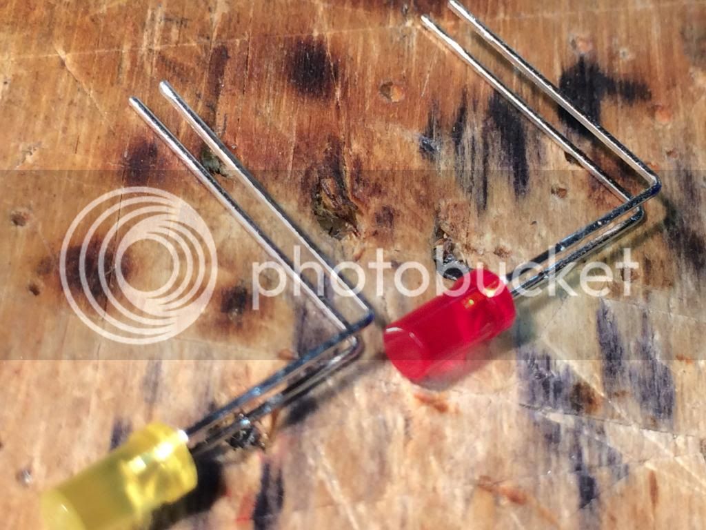
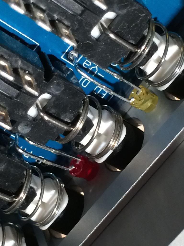
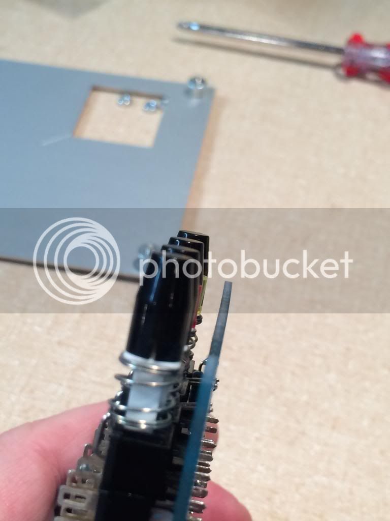
The LED's are not in line with the switches, they are offset.
Line the back of the LED up with the edge of the PCB
Mark and bend.
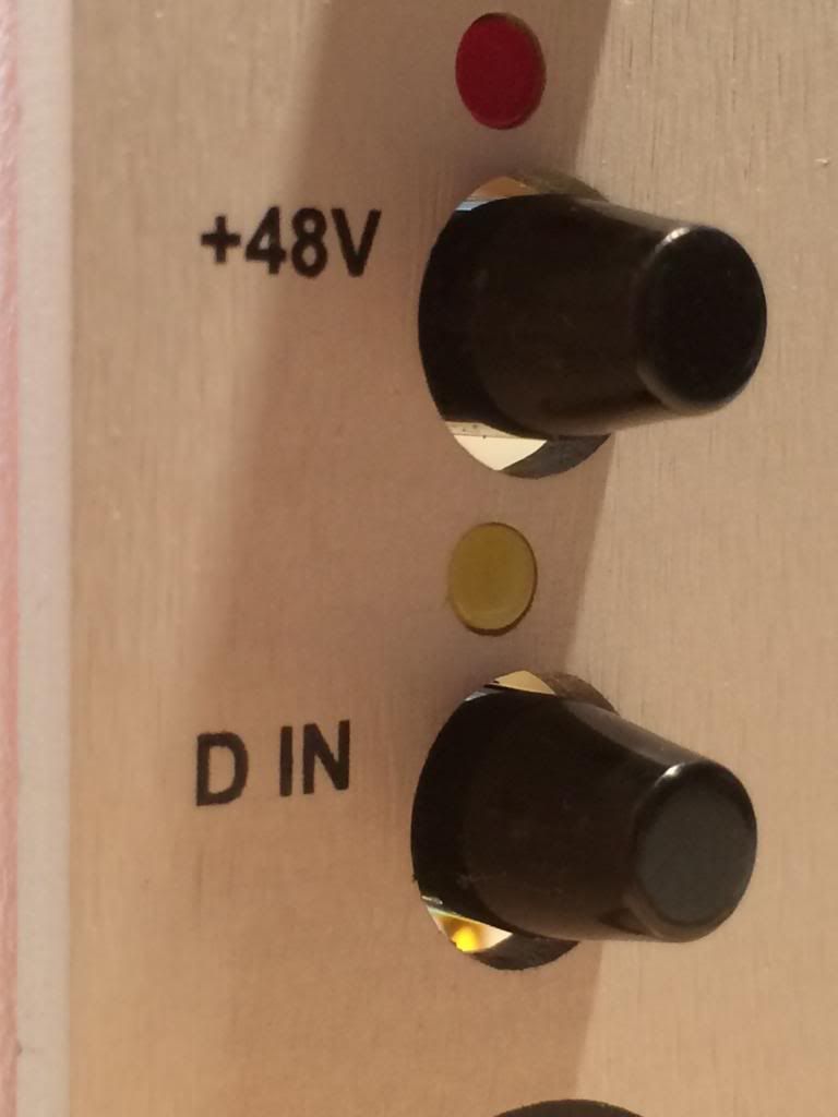
They stick out when installed.
Then you can push them in after installation and make them perfectly flush.
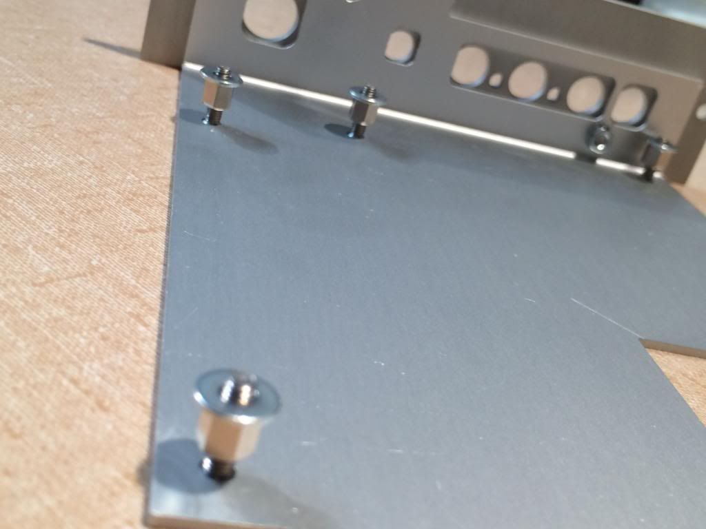
Further alignment details. The front panel is mounted with two screws. They fit in a slot that allows movement in 2 dimensions, so you can realign the front panel after installation. The holes are not enough adjustment for the misalignment of the front panel, you will need to install washers or the switches will be held to one side of the panel holes. Larger standoff's could also work.
Washers on the standoff's. I used 4/40 washers which worked with the M3 screws included in the "small kit".
They hold the PCB up and allow the front holes to align with the pushbuttons.
All you need to do is position the switches properly on the PCB, and align the switches. As long as the switches are positioned normally and aligned with one another, you will be able to adjust the front panel to make the space around the switches equal.
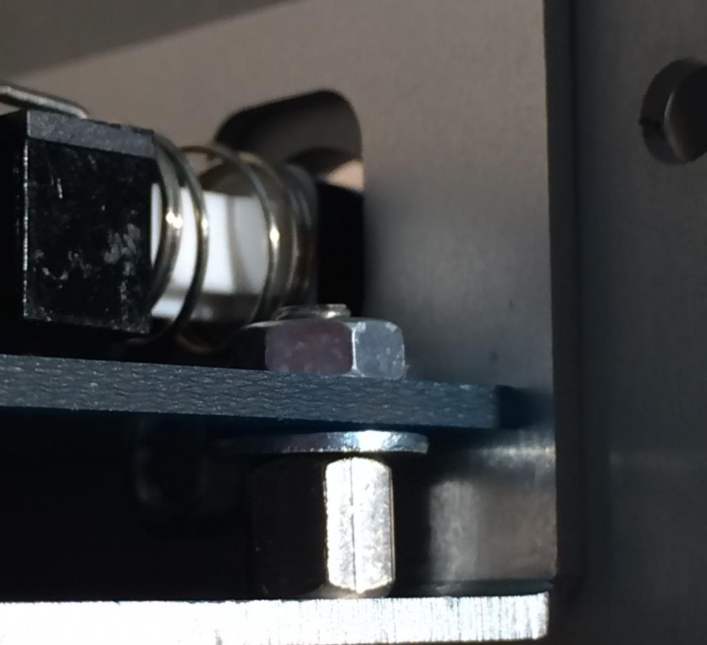
To tighten the front panel screw, you might need curved needle nose pliers, or maybe a longer screw (M3) and a lockwasher.
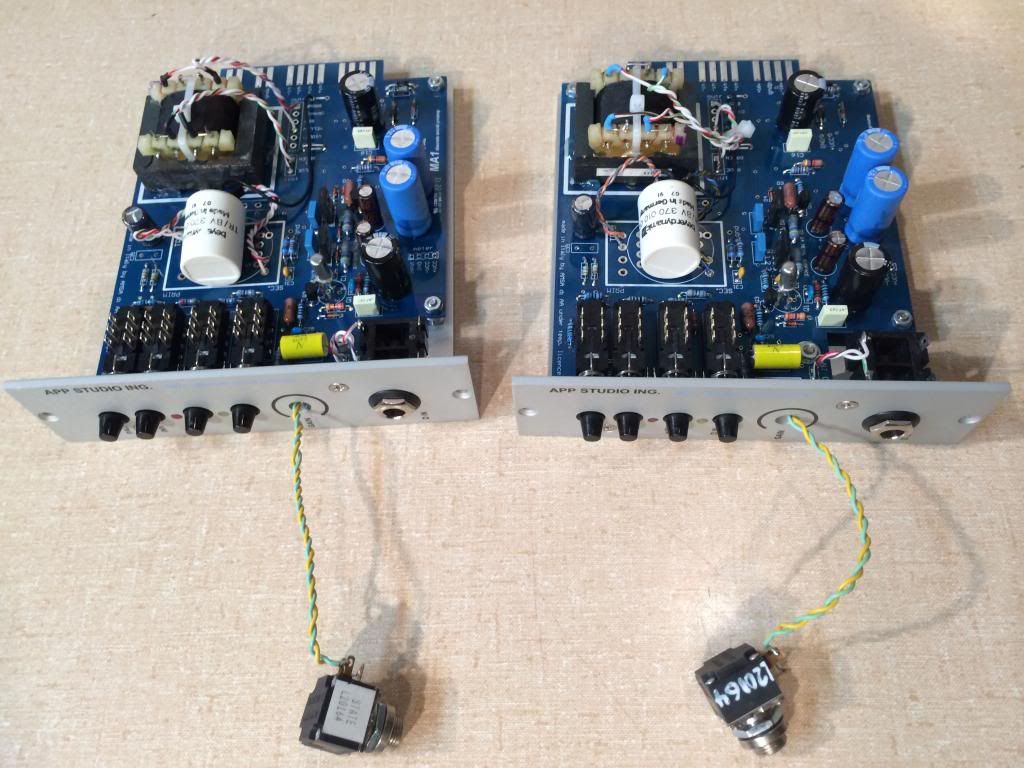
The two preamps are "complete" using my found components. I may change the transformers, and I will certainly change the pots because they won't fit (they were the only revlog pots I had lying about). May try to fit a stepped switch in there or I will buy the Bourne pot recommended.
I used these little Beyers. Shield and case go to the star ground point.
(
I have not does noise or response curve tests yet. I did notice that at high frequency I get a relatively large amount of phase shift, and that when passing square waves the "slew" rate is pretty slow. Is that a characteristic of Germanium designs or is it my transformers? - It was neither, it was my test setup. My cable had only one side connected!).
Don't know what they sound like yet, I can't do more till I can mount the pot. But it is an easy build and a well made kit.
A lot of this is mentioned elsewhere in the thread, but here is what I would tell anyone building the project:
1) You need to put a strap in to connect the transformer. You need to tie the ground somewhere (strap will make it a star ground tying Pin1 and power on the module).
2) alignment is easy because the holes have lots of clearance, and the front panel can be shifted on the carrier, but I needed to put washers under the screws to make it fit.
3) you need a curved needle nose pliers to reach the bolt on the back of the front panel screw, a longer screw with a lock washer might work better.
4) I recommend hand matching the 6.8k resistors to better than 1% with a DVM (this is just good practice).
5) The board itself (the PCB) is thinner than the 0.062" I am used to, it measures more like 0.057" thick. This has two effects. One the board flexes a bit when aligning (not a problem). Two when you seat the module in the rack it feels like it hasn't reached the connector, but it did it just slides in real easy because it is a bit thinner.
6) The carrier is beautiful, nicely made. They are beautifully countersunk, thick, and the bend is sharp and clean. Both of mine were a little "acute" and I had to flex them open a bit to get a 90 degree angle and make the board fit easily.
7) The AC126 mounts with it's "tail between it's legs" in order to get the pins right, see the pictures elsewhere in the thread. I soldered mine in the end, but the pictures I used sockets in case I goofed.
8) There are inconsistencies between some of the schematics and the BOM, but the BOM is correct except for C36 which needs to be greater than 50V. If you bought a kit, Pier included the correct cap.
Thanks PPA for great design and execution, and for being so responsive! This was a pleasure to build. I think the whole kit could be built in 3 to 4 hours working carefully if if one had all the parts in stock.


")