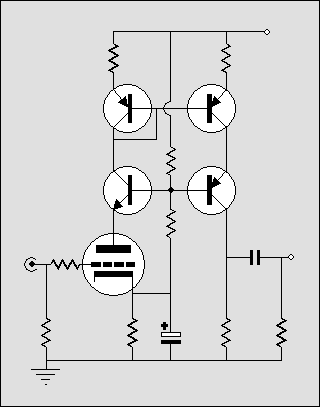
Mic amp idea

GroupDIY Audio Forum

Help Support GroupDIY Audio Forum:

This site may earn a commission from merchant affiliate links, including eBay, Amazon, and others.
A good starting point for experiments, based on some quick calcs:

12AY7
230V B+ (after filtering)
1K cathode resistor
47K plate resistor
10:1 output transformer

Net gain from V1A grid to transformer secondary is about unity. Source impedance of V1B is around 20K, transformed to ~200 ohms at the output jack.
 
Dave, what do you think of this Miller-Busting Cascoded Current Mirror using sand?
Reflection_9.gif


Low Miller (if you keep Re low) + Feedback & Gain.

http://www.tubecad.com/2005/January/blog0027.htm
 
Like my Grandma said, "It all mixes in the same stomach"

Unless you Home School your sound, it's gonna find transistors to hang out with. I mite make this one too. Heat up the tar..
 
Another way to make use of both sides of an AY7 in a mic amp. This is essentially the Church circuit with a cathode follower in front.

MicAmpIdea2.png


Those extra parts net you about 6dB of gain compared to the previous circuit... maybe worth it, maybe not.
 
:thumb: Direct coupling em was where I choked. Taking V1b's own grid leak feels better.=) Ahh.
I will of course, try to build both, bro. I need a triode body for this capsule. I already have a pentode one.

I bet this could be the 10 foot tall acoustic guitar mic!

Right now, I'm trying to figure out how wide and long of a pencil line on paper is 200 mohms.
 
...and here's another, more conventional idea:

MicAmpIdea3.png


This'll probably be the first one I try because 12AY7s have become too expensive for my liking.

I predict a net gain of a little over unity and a transformed source impedance of 150 ohms or less.

Was the (tube shown in my schematic) ever used in a commercial mic? It seems like a natural choice but I don't recall having seen it. (As for preamps, that's a different story, of course).

PS: Yes, I know I'm exceeding the grid #1 resistance spec. But it's worth trying out to see if it'll really be a problem.
 
Are those rascals at Church getting negative feedback by connecting the low side of the xfmr primary to the cathode instead of ground, and putting the blocking cap on the low side? cheeky.
 
<Like my Grandma said, "It all mixes in the same stomach" >

Or, as my cousin from Memphis muttered at Thanksgiving, "I don't care what it tastes like, as long as it makes a hard turd" :shock:
 
The core problem is that one tube inside a modern mike housing is HOT; two tubes (or a twin-tube) is too-hot. One tube is all you need to mate with dynamic mike preamps.

The Miller is not killer. It reduces output, but condensers have tons of output. As everybody knows (I assumed), or learned in that paper that was linked here recently, a condenser mike is square-law so has distortion, which is reduced if you throw a significant capacitance on it.

You will also have a noise problem using the self-bias resistor to couple the CF to the GG stage. The CF will run at gain much less than unity, and the total noise appears to be double that of one tube. Yes, the high output level of a condenser makes that less critical, but you can't get careless.

The low/medium-Mu lo-noise triode with step-down transformer seems a reasonable plan, confirmed by about 567 commercial designs.

Tube mikes will be lowest-noise with ~~200Meg grid resistor. A little higher for special mike tubes, a little lower for common tubes. Use 100Meg. Save the 1G for FETs.

If plate resistor and supply voltage conspire so that the plate dissipation can NOT be approached, don't worry too much about violating the grid-leak rating. If plate resistor is much higher than plate resistANCE, and Mu is fairly high, the tube tends to find its own bias point. You may have to burn-in the tube, and weed-out gassers, but it should work.
 
701.jpg

Jesus, Mary and Joseph! look what I found looking for tubes to use. A brand new, unsoldered AC-701 in the box. Not a "k" But not a fake either. I hope it's self-noise is Telefunken-gruuven.

This should run cool enough, eh PRR?

I remember Dale explaining why Miller Effect was good for mics now that PRR mentions it. Dang square-law. It's so outdated, daddy-o. :cool:
 
the 2nd schematic looks like the vm1 fragment I shared some time ago.

It will be close to the operating point of the cathode biased vm1 and fixed bias U67 and my square microphone.

I was wondering how long it was going to take before someone remembered the Dale posts.

Read my posts in the microphone threads the grid resistance issue was addressed using tubes and if you wan to get fancy you need to think about the oxides and alloy type of the heater.

Pentodes as triodes in a tube microphone done all the time.

The work I gave away and people miss it.
 
[quote author="PRR"]As everybody knows (I assumed)[/quote]

I didn't know about the square-law response of the capsule. Then again, I only became interested in the internals of mics very, very recently. For 20+ years I've been looking mainly at what comes after the mic, and considering the mic a black box of sorts. Transducers are a deep subject in themselves.

The low/medium-Mu lo-noise triode with step-down transformer seems a reasonable plan, confirmed by about 567 commercial designs.

Triode-strapped 5 8 7 9 is common in a mic preamp but I haven't seen it inside a mic yet. Then again, I haven't looked at all the schematics out there.

Tube mikes will be lowest-noise with ~~200Meg grid resistor. A little higher for special mike tubes, a little lower for common tubes. Use 100Meg. Save the 1G for FETs.

Yeah, I was thinking about that on the drive to work this morning. You'd be hard-pressed to find a tube that isn't going to develop fairly significant contact potential bias across a ~1G resistance. I guess that 'splains why 200M seems to be the often-used value in the tube mics I've seen.
 
I own a couple of the Groove Tubes (Alesis) AM62 mics.

This mic sports a sub-miniature 5840 tube (pentode) as a triode. The polarizing V+ through a 2 gig R. It looks like they didn't strap G2 or G3, but left them open.

Grid R= 670Meg
Grid Cap= 6.8nF
K Cap = 1k
K Bypass = 330uF polar
B+ = @123V
A+ = 5.9V
Plate R = @20K

Common K setup, slightly high noise floor.
 
I have not been inside the am62 but a friend has some and told me G2 is the plate and g3 connected to cathode inside and the plate are not connected. Now something like this can be found in books but the plate is grounded.

I have posted in the past about the different triode as pentode connections, two that you see u47vf14, c800G 6au6 G2 and G3 to the Plate

U67 ef86 G2 to the plate and G3 to the cathode

The only thing I found about the different hook up is in the big red book with different noise for different tube with the two hook ups. Some tubes have G3 connected to the cathode so it is the only hookup you get
 
I re-checked today... Out of five leads from the tube:

Gate 1 - Gate
Gate 2 - Plate
Gate 3 - Cathode

Heater + and -


The PCB is hard to follow for me... I'm still a newb at that.
 
[quote author="Larrchild"]Are those rascals at Church getting negative feedback by connecting the low side of the xfmr primary to the cathode instead of ground, and putting the blocking cap on the low side? cheeky.[/quote]

I thought the same thing at first glance, then noticed that the cathode is bypassed.

I'm not sure why they coupled it that way. I can only suppose that some advantage was seen in placing the cap at the AC-grounded end, and reducing the DC potential across it by a couple of volts compared to the usual method of coupling.
 
> but the plate is grounded.

If you are going to use a pentode as a triode, the only difference between the plate and sceen is power dissipation. And if your Pd is less than the screen's rating, there is no real need to bring the plate into the picture. And if instead you ground the plate, you have a pretty good electrostatic shield around the tube. BBC did this a lot. Low power circuits, pentode screens used as triode plates, original plates used as shield.

> You'd be hard-pressed to find a tube that isn't going to develop fairly significant contact potential bias across a ~1G resistance. I guess that 'splains why 200M seems to be the often-used value in the tube mics I've seen.

Well, there's that too.

The grid resistor has a thermal noise power. This gets shorted-out by capsule capacitance. For this reason alone, we want the highest possible resistance.

BUT. Tube grids have noise current. This multiplies-up to a voltage in the grid resistor. For this reason, we don't want an excessively high grid resistor. FET gate current noise is (can be) far lower. 1G seems to be OK for grid current noise, and capsule capacitance shunts thermal noise of 1G better than 100Meg.

The capsule capacitance is a frequency-dependent "short". At the highest frequencies, it may not matter what resistor you use. (Anyway if the total design is good, HF noise is dominated by air resistance.) It seems that grid current noise should dominate at very low frequencies. How your ear balances this with MF and HF noise, and room noise, is a matter of opinion and use. There is some info in a 1967 AES paper by James Noble.

Most of this seems pretty broad-optimum. If 234Meg were "best", probably 100Meg and 500Meg would sound the same.
 
ok gus, we get it, youve posted a lot of stuff
:grin:

food for thought: cj,nyd and prr all have over 3000 posts each... but they dont get all indignant when someone asks about something theyve posted about before. your contributions are very valued by all of us but please dont take it as a personal affront when someone talks about some aspect of microphones that you may have touched on before.
 
Back
Top