Microphone design tutorial part 3

GroupDIY Audio Forum

Help Support GroupDIY Audio Forum:

This site may earn a commission from merchant affiliate links, including eBay, Amazon, and others.

mista min

Well-known member
Joined
Jan 21, 2011
Messages
113
OK, so I don't own either one of these microphones and there was once a thread discussing one of these, but here are two schematics for two CAD tube mics.  The no longer made, VX2 and the still manufactured Trion 8000

The VX2 schematic and owners manual
http://dl.dropbox.com/u/13352325/DIY/vx2_schematic.pdf
http://dl.dropbox.com/u/13352325/DIY/CAD%20VX2%20Owners%20manuel.PDF

Trion 8000 schematic, power supply and spec sheet
http://dl.dropbox.com/u/13352325/DIY/TRION%208000%20SCHEMATIC.pdf
http://dl.dropbox.com/u/13352325/DIY/PS120-SCHEMATIC.pdf
http://dl.dropbox.com/u/13352325/DIY/TRION_8000_spec.pmd.pdf

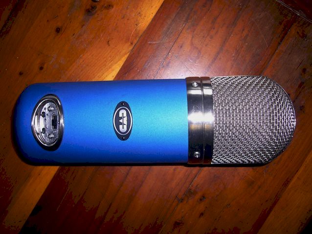
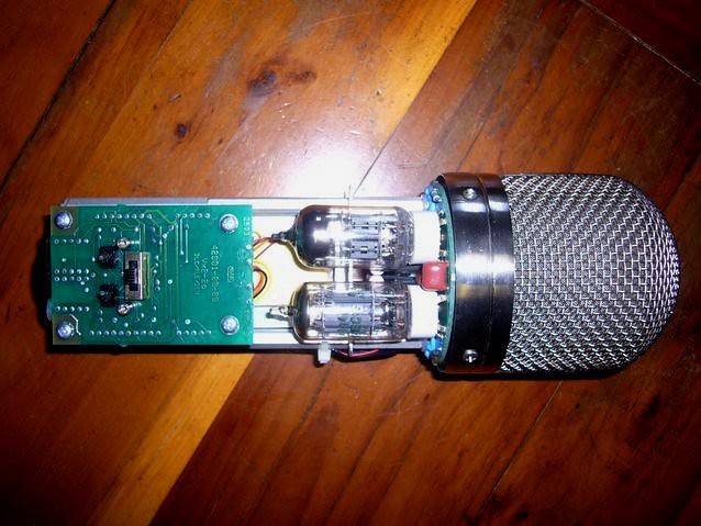
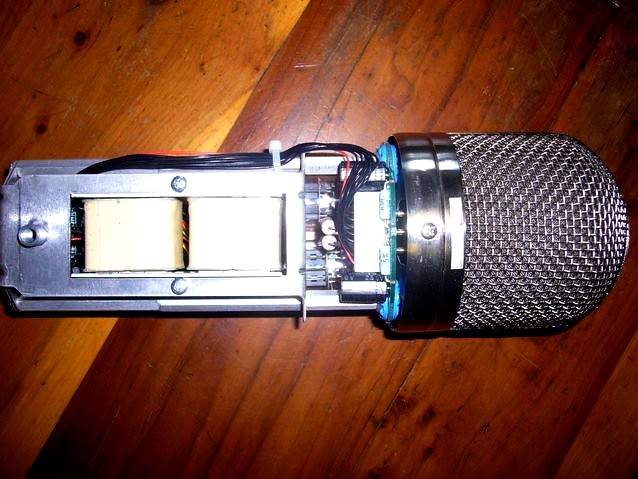
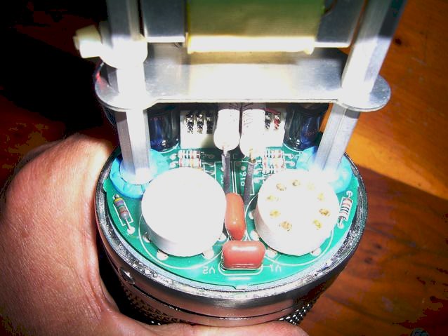
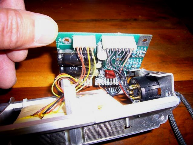
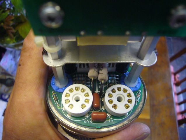
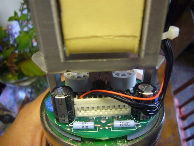
I hope we can discuss these mics a bit... since these designs are pretty interesting if you ask me.  Also, could someone post pics of the insides of these mics... there is a thread about the 8000, but no more photos.  Thanks you guys once again, this forum is helpful to many :)

Cheers!
Marcos
 
No replies? :(

Then I'll post, I think it's interesting how they use two dual triodes.  Each side of the capsule goes to a one half of each tube.  Also, they use a 12ax7 for the first part of the mic.  Interesting!

Anybody else?
 
So once again no replies, but hopefully this might interest some... here are some photos provided by flinty from Gearslutz.com
5700760935_6c8478bd94_z.jpg


5701345718_3a6f031507_z.jpg


5700790311_f6991c3e95_z.jpg


5701371772_91f3925ca1_z.jpg


5701381608_87c55349cb_z.jpg


5700734033_4aecd1428d_z.jpg


5701303920_5577bcef06_z.jpg


Ok, so big thanks to Flinty for the photos.  I hope to have power-supply pics up too, but this should get us rollin'.

Cheers,
min
 
Thats a interesting schematic and Mic.... How does the Vx2 sound?

That Triton has a 6J1 tube which translates to a Chinese copy of the EF95
 
Honestly, Idk.  I have read a few threads here and there and it's been called CAD's "best" sounding mic.  I haven't been able to try one out and they go for about $1000 used, which isn't a lot, but more then I can currently afford.

What's making me trip out is the use of a high gain tube in the first portion of the mic.
 
Wow... not many comments... so I will ask the question that I can't answer myself.  Why?

Why use two dual triodes and two transformers on a mono mic?  Why use a 12ax7 as the first tube?  Won't the 12ax7 have a large gain factor (Are R18 and R7 the cathode resistors and are they introducing negative feedback and a really really really dumb question, how?)??  Maybe someone could answer these questions.  Also will someone explain how the two unattached portions connect on the schematic? 

I think it's cool that it's so different then every other schematic I've seen.

Where do the J1's connect after the tubes?  I didn't wanna ask because I am embarrassed about my lack of knowledge and hoped someone would explain some things.

Thanks,
Marcos
 
Each half of the capsule is coupled to a dual triode stage, their o/P's (pins 8&9) are balanced by one xformer each, their secondaries are connected through SW3, which accomplishes the generation of the overall polar pattern by including or excluding the o/p of the 2nd stage (rear capsule) in the signal path... in phase = omni, out-of-phase = figure-eight, and n/c (top and bottom of the secondary shorted) = cardioid.

Quite an unusual way of doing it, since it involves 2 double triodes (= heat generation, lots of filament current required) and 2 xformers (cost factor). Normally, you'd change the pattern by summing the signal of both capsule halves into ONE amp but changing the polarizing scheme of the capsule itself. In the CAD mic, you only need to polarize the middle of the capsule with a fixed voltage, but I doubt that this is the reason for the double amp design ;-)

Maybe they wanted to come up with a design that doesn't change in o/p level if you switch patterns (which can happen with some pattern selection schemes and summed capsule signals before the amp, as each capsule half may load down the other and result in a capacitive voltage divider.

The lo-cuts are realized by SW1, obviously electrolytics are used to set the frequency, which may result in a considerable unit-to-unit variation of the cutoff, due to the large tolerances that electrolytics have.

As to the 12ax7 thing, the amp stages have NFB from the second anode (pins 9+8) back to the first cathode. NFB reduces distortion and noise, but someone else will have a more detailed opinion on this... check e.g. AKG's C12 VR, they use a 12ax7 in there, although the 2nd stage is not used for amplification but IIRC a filter stage or something, and the first stage is run open loop (again IIRC)

BTW check for the numbers near the J's, they correspond to the numbers of those on the other half of the schem.


Dude thanks for all that info, but I'm not following concerning tubes using the anode to cause NFB... forgive my ignorance, but I do see it on the schematic :(.

Also, I thought the pin-outs were different?

This is what I found on wikipedia (I know, I know, but it has pretty colours :D )
http://en.wikipedia.org/wiki/12AX7
EIA-9A.png


edit... I keep looking at it and I think I see what you mean, but I don't understand electronics enough to know what it's doing... how is C8, R15 and R13 effecting the NFB loop (that's what you mean right?)?  Could someone please tell, because this would be good for me to understand :/

According to this figure it's pins 1&6 going to 7&2.  Please clarify, thank you!
 
Thanks for the photos. Going on from Volki's nice analysis, I always thought someone missed a trick with this microphone.

Having gone to the effort of amplifying the two signals separately, they then combine the signals in the microphone. Had they given separate outputs for the two head amps, they could have had something like the Josephson C720, or the other mics discussed here...

http://www.groupdiy.com/index.php?topic=44075.0

But it does look like a fun mic. I've nearly one to try on two occasions, but the deals didn't work out.
 
thanks for posting the pix ,
interesting as i recently modded an apex mic
to have two sets of electronics and two separate
outputs , it's kind of dry , very stereo sound
wonder if you could do that with the cad

Max's latest 47 variation uses two tubes [ what kind ? ]

Also classic for many 12A tubes  plare/grid/cathode
heater/heater/plate/grid /cathode/heater
memorized it like a nursery ryth [ looking from the bottom  clockwise ]
 
okgb said:
Max's latest 47 variation uses two tubes [ what kind ? ]

I believe they are 12au7's in the pictures

okgb said:
Also classic for many 12A tubes  plare/grid/cathode
heater/heater/plate/grid /cathode/heater
memorized it like a nursery ryth [ looking from the bottom  clockwise ]

Love it!  Already helping me memorize it!
 
mista min said:
okgb said:
Max's latest 47 variation uses two tubes [ what kind ? ]

I believe they are 12au7's in the pictures

Actually, he uses two 6028 tubes in parallel.
These are kind of odd tubes in that the heater is 20V.


mista min said:
okgb said:
Also classic for many 12A tubes  plare/grid/cathode
heater/heater/plate/grid /cathode/heater
memorized it like a nursery ryth [ looking from the bottom  clockwise ]

Love it!  Already helping me memorize it!

In my opinion, datasheets are more reliable than mnemonics.

 
Mista min, I think you're mixing up pin numbers of the tubes & pin numbers of the connectors that link different parts of the circuit. You've got two connectors (J1 & J2), with corresponding numbers of pins each. I was talking about those, not the tube pins.

Since you asked for a discussion of the circuit, I was assuming that you know the different elements of a tube and what they do. I recommend going to this thread, scroll down to the bottom of the first post, there are some links regarding tubes and tube circuits. Then re-read the posts above.

 
zebra50 said:
Having gone to the effort of amplifying the two signals separately, they then combine the signals in the microphone. Had they given separate outputs for the two head amps, they could have had something like the Josephson C720, or the other mics discussed here...

True actually. So a very simple mod would be to disconnect the xformers from the pattern switch and wire them to the XLR connector separately (there are two unused pins), and put the switching arrangement in a small extra box (or the PSU, even), and of course make it defeatable so you can use the two o/p's separately. Provided that the cable to the PSU doesn't have any unused leads, you'd simply use another standard mic cable (2 leads + shield) in parallel.

 
volki said:
Mista min, I think you're mixing up pin numbers of the tubes & pin numbers of the connectors that link different parts of the circuit. You've got two connectors (J1 & J2), with corresponding numbers of pins each. I was talking about those, not the tube pins.

Since you asked for a discussion of the circuit, I was assuming that you know the different elements of a tube and what they do. I recommend going to this thread, scroll down to the bottom of the first post, there are some links regarding tubes and tube circuits. Then re-read the posts above.

Sorry, I see it now.  When you said pins I thought you meant tube pins.  Thanks for explaining it makes a lot more sense.  I was having trouble connecting the two half's of the schematic.  Also for the links, since I can use some of those equations from that page to calculate how the feed back works.  Why did they use a 12au7 as the second tube?
 
Interesting schematic that CAD VX2 - but indeed quite some additional hassle, while the advantage of doing so doesn't seem too clear  ???

The SOS-review mentions for instance: "The omnidirectional pattern was a little disappointing though, as it seemed to become almost figure-of-eight in shape above about 6kHz — you could certainly hear the effect when it wasn't on-axis to the source!"
... probably capsule related, or ...  actually because of the non-usual arrangement perhaps ? ... since the summing/subtraction is done after many more components can have had their (bad) influence on the matching of the two signal paths.

volki said:
The lo-cuts are realized by SW1, obviously electrolytics are used to set the frequency, which may result in a considerable unit-to-unit variation of the cutoff, due to the large tolerances that electrolytics have.
Note that the values of these elco's don't define the HPF cutoff-frequency: the linear (off) position does indeed use C16, C17, but the highpass-filtering uses just C18, C19, which seem to be film-caps. FWIW...

Also interesting they do the pad by changing the polarisation voltage. Not new, but if I'm not mistaken less common than by switching a cap near the capsule for attenuation.

Indeed a strange move to ignore the possibility for two separate outputs, they're almost there.


I wonder about the ratio of these transformers. What kind of load would be nice to present to the output-tube V2 ?


Regards
 
The ref cardiod thread reminded me of this thread. The schematic was interesting IIRC.

A different circuit however it used a 12ax7 and 12au7 with two amplifier sections
 

Latest posts

Back
Top