Mister Graphic is VERY happy today...

GroupDIY Audio Forum

Help Support GroupDIY Audio Forum:

This site may earn a commission from merchant affiliate links, including eBay, Amazon, and others.
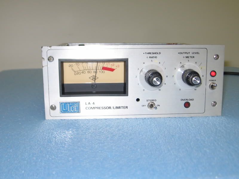
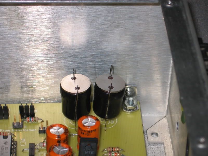
Here's a pic of the two end-caps installed:

IMG_5836.jpg


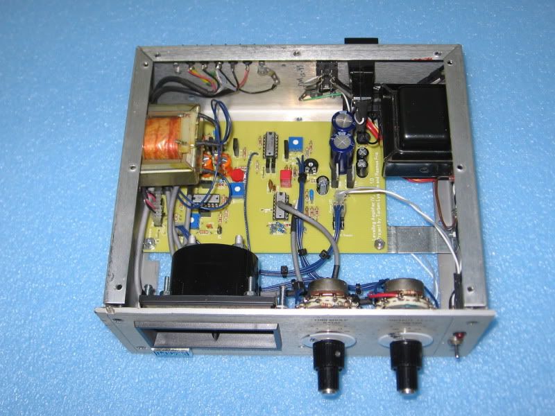
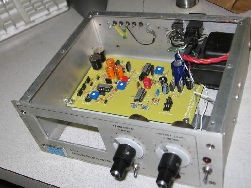
-And the board, mounted in its new home:

IMG_5837.jpg


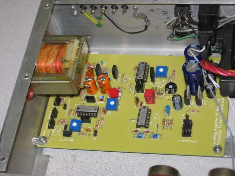
I took the output transformer from the 533 graphic, but it's PCB mount, so I opened up the frame, remove the transformer and re-inserted it upside down, so that it can now be chassis mounted without the terminals shorting against the side panel.

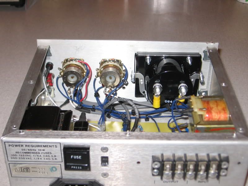
Here's the transformer mounted:

IMG_5838.jpg


IMG_5839.jpg


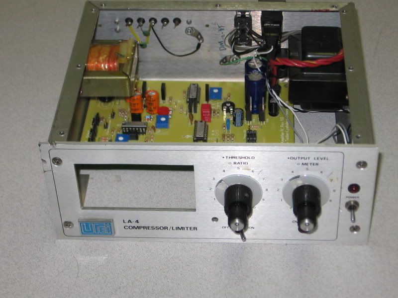
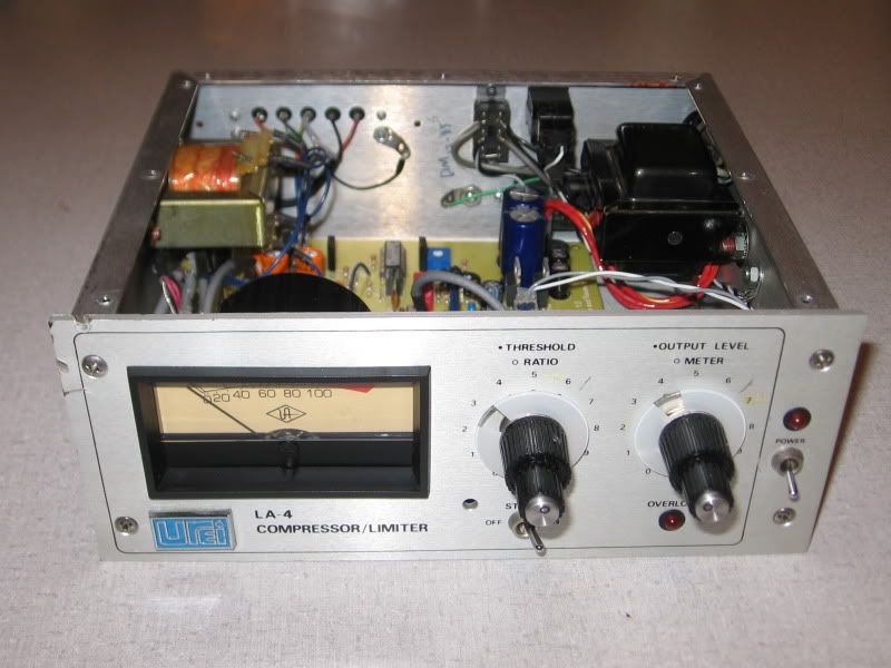
-And one with the meter mounted:

IMG_5840.jpg


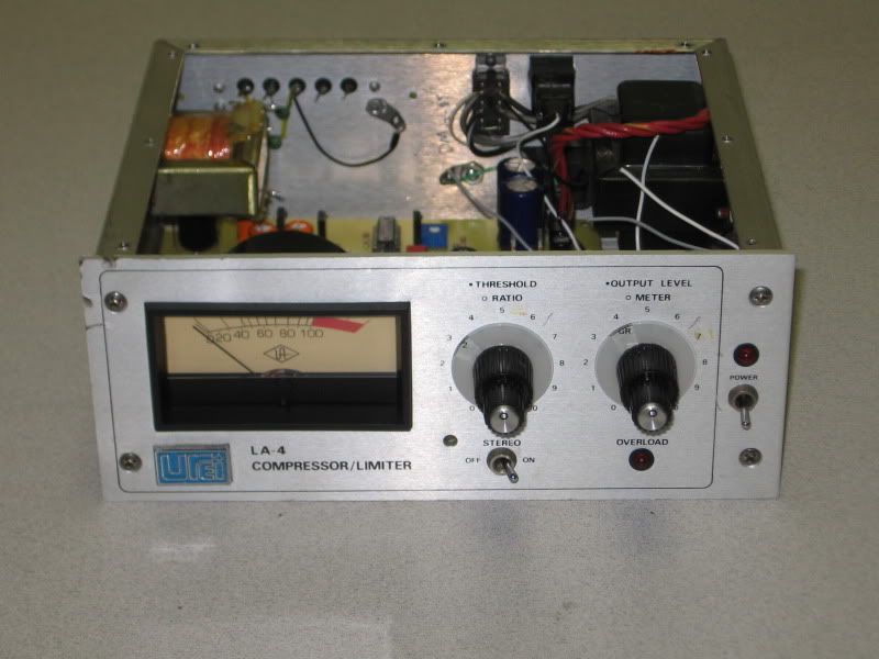
Now... that's pretty much everything mounted.  -On to the wiring up!

Keith
 
I see you couldn't resist taking the blue UREI badge of the 533 front pannel and stick it to the LA4 8)

Axel
 
I do have a second power transformer, output transformer, pair of optos and LEDs, and the black light-caps that I found...

If anyone ever DOES want to build another one, it would be a great way to get all of the important parts in one go... including the original iron etc. -I just have the one set though.

Let me get this built, tested and auditioned, to make sure that it sounds right. -I have a couple of black face and silver face units to compare it to once it's built and calibrated.

-I wish I had another front panel, but if I did... I'd be building a second unit instead of offering this stuff for sale.

Keith
 
Got the PM. Let me get it tested and make sure it's all good.

Just finished wiring it all up...

Inside:

IMG_5841.jpg


...and the front panel inside:

IMG_5845.jpg


Looks pretty good.

IMG_5843.jpg


Power up initially. -I'll take it in to work tomorrow and see how it traces on the analayzer.

But... when I gave it a quick power up, there's no smoke, and the 'GR' position looks like this:

IMG_5842.jpg


Voltages look good, and no smoke. -Humans win!

;D

Keith
 
Woo-hooo!!!

Plug in audio... all levels look GREAT! output level Meter is SPOT-ON, distortion is RIGHT on the money, at right about 0.025% THD+N.

IMG_5847.jpg


...yes I know, the meter is switched to 'GR' and not output, but the distortion measurements should be made with the switch in this position... you'll hve to take my word for it, the meter is SPOT ON in the +4dB position, and about an eighth of a dB off in the +8dB position!

But...

No compression at all... -Hmmmm. -I wonder why?

-I decide to scope looking for audio signal at the wiper of the threshold pot. -Nothing. -I look for audio signal at the top of the pot... nothing. -That'll be my problem though.... but why?

Two seconds of looking at the schematic tells me why... -I didn't notice that I needed to add a 2.2k resistor between the 'top' of the two potentiometers... sixty seconds of soldering and heat-shrinking later, I power back up, and.... SUCCESS! -Compression!

A couple of minutes dialing in the GR meter tracking and VU zeroing (for which is best to throw a little piece of cloth over the LED/Optos, since a TINY bit of light leaks in through the ed plastic of the LED bodies) and the meter tracks PERFECTLY!

Five minutes dialing in the adjustments as per the LA4 calibration instructions, and everything works  PERFECTLY!

IMG_5848.jpg


Here's a close up of the ratios:

IMG_5849.jpg


...which basically looks EXACTLY like it should! (Ignore the little 'kink' just below the threshold in the 4:1/8:1/12:1/20:1 curves... the A2 was set to low resolution for super quick sweeps. -The actual curves are DEAD-ON!)

LA4ratios.png


HUMANS WIN!!!

I'd like to extend my deep thanks to the guys who did the board layout. -Even though it was a little tricky squeezing it into the graphic case (which this layout was never designed to fit into), there wasn't a SINGLE problem with the build, or the board (thanks Gustav!) and the only MOMENTARY issue was with my own overlooking the 2.2k resistor on the front panel, which set me back for all of two minutes I think.

One of the easiest and most pleasant builds I've ever done... -EVER!

Now to get deep into the investigation stage, and see what I learn.

Oh, by the way... the output transformer is wired STEP-UP.

Keith
 
Running signal and measuring the output signal before and after the transformer reveals that it has a voltage ratio of 1:1.5. -That sounds about right since it'll give an impedance ratio just over 1:2, and the DC resistance of the primary is 9 ohms, DC resistance of the secondary is 19 ohms.

Frequency sweep looks good also. -Still fairly flat an octave above and below 20-20kHz. -Good enough for me!
 
Hi Keith,
I have two questions for you regarding the wiring of the Ratio Switch Of the LA4 , (i saw that you buil it in the box of the urei graphic eq)
I have followed your schematics extracted from the original urei manual but i have a problem with ratio calibration of the unit
It seems to compress more at 2:1 ratio than the 20:1 ratio ...
Can you tell me how to connect the lorlin switch and how to calibrate this section of the unit ? because in the original manual is not clear.
Let me know
Thank you
Fabio
 
"compress more" -well it all depends on the threshold.

The threshold is automatically switched to be more sensitive in the 2:1 position. -Hence you can see the 'knee' occurs at a much lower level.

I don't understand the question about how to wire it... it's wired just as in the schematic.
 
Keith ,
As i say, i followed the manual for wiring but i don't know the right calibration procedure (the urei manual calibration procedure is not quite clear) .
Can you tell me step by step how to calibrate the unit correctly (like yours ) ?
Let me know
Thank you in advance
Fabio


SSLtech said:
"compress more" -well it all depends on the threshold.

The threshold is automatically switched to be more sensitive in the 2:1 position. -Hence you can see the 'knee' occurs at a much lower level.

I don't understand the question about how to wire it... it's wired just as in the schematic.
 
Back
Top