Note about VCA.
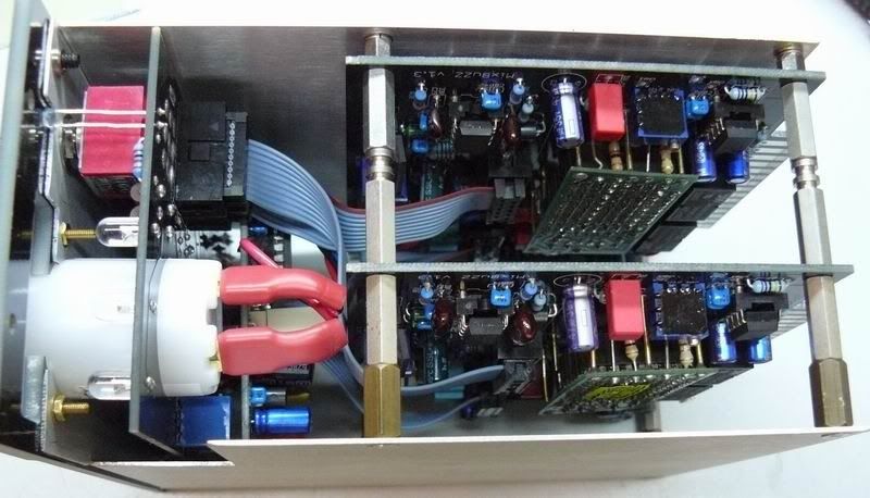
I tested this compressor with DBX202X, replacement board with 4xTHA2181( A and C),
and replacement board with 1xTHAT2181C. For other VCA's, R100, R3, R4 on audio board can be different.
DBX202X has internal resistors on inputs 8x10K, than, input resistance should be skewed
by 1k25. Control port impedance is 832 Ohm. I.e. R
6=3k74, R3=4k99, R100=909R.
On VCA replacement board supplied with kit, there are 4x2181 VCA's, input resistors are 4x20k,
and control port impedance is same as 202x 832 Ohm).
I.e. R
6=jumper (0R), R3=4k99, R100=909R.
For "more sound" use only one THAT2181C, bit misadjusted for more harmonics.
In this case, install only one VCA and according resistors on input board,
no change in control port circuit (NE5534, 100R, 732R).
In this case, R3=20k, R
6=0R (jumper), R100=909R.
It is possible to lower C1 down to 22pF.
/BOM values are right.
For other VCA's, refer to datasheet for input, control port and output resistors.
DBX VCA datasheets can be found in useful_stuff1.zip
Sidechain VCA's.
Simplest and cheaper solution is THAT2180C, don't install SC_SYM trimpot and R33.
There's no need for A version VCA in sidechain.
Trimpot adjustment.
Adjust for minimum distortion with analyzer (audio) and 0mV dc offset (sidechain).
Don't have analyzer?
Sidechain: adjust for 0.0 mV DC at IC11a, NE5532, pin
1
Audio: adjust for 0.0 mV DC at IC11b, NE5532, pin
7
{fixed}
Sidechain trimpot (RV1) on audio PCB: changes threshold point... install 5k1 and forget.
Threshold trim (TR_TRM): changes threshold zero. Omit (install nothing) and forget!!!
(Or use side screw, 50k, 10(25) turns trimpot to change 0db threshold point @ratio=4).
Added at July 11th.
Some words about testing the unit.
IMHO, easy way to do this is connect power supply to all boards
via 3-pin Molex connectors and use pair of same cable assembly's for audio.
I.e. take 5 of Molex 3-pin/2.54 pitch connectors,
MOLEX - 22-27-2031 #9731156
MOLEX - 22-01-2035 #1697895
MOLEX - 08-50-0032 #9773789
SOLDER 20-25cm wires to "crimp" pins;
Than, connect 3 of wire assembly's in parallel-this is for power supply.
Feed audio in/out via 2 wire assembly's left. If somebody need picture,
tell me to post.
--------------
Other way is testing inside the 51X (500) rack.
Take other modules from rack (if your 51X rack is full of them

Solder 3x25 cm wires from front panel PCB power supply
connector to one of audio PCB's, and use longer (20-25cm) ribbons.
Check CTL and SC ribbons goes to according boards, say, CTL1/SC1 to left etc.
Put audio PCB's inside the rack, to slots...say 3 and 7.
This way, we have some space inside the rack to put scope probe or multimeter.
Check unit is passing audio with unity gain (make-up at 0) and measure DC offsets.
If audio PCB's soldered without mistakes, it should power up fine from first take.
The rest is just test the ratios and maybe change R60.
------------------------
Update July 12th.
Ratio calibration.
There's lot of info about this, search forum. Just want to add some
info gathered from building some MixBuzzeZZZZ
and real life experience with nice 4000G lady.
Actually, this is feedback compressor which is built across sidechain VCA.
After all, the control signal for sidechain VCA mixed with MAKEUP control voltage,
/sorry my english

/ than controls AUDIO VCA.
The ratio of "sidechain compressor" is a bit higher than actual audio ratio.
Mind, there's no log converter and linear rectified signal controls log VCA's ports.
There's kinda slope limiter after 1.3v threshold at ratio "1:2", but,
this is not logging, again.
To be at perfectionist's side, it is possible to measure the sidechain's ratio first
by measuring signal at IC11A, pin1, applying first signal 2db down threshold
(not to be misunderstood, 2db gain reduction), than
applying 10 or 20db more and measuring output again at IC11A, pin1.
If 1% resistors used, I think, it is useless procedure, but...just to be at safe side.
My sidechain ratios were constant for all builds, about 2.1:1, 4.3:1 and 10.5:1.
Than, we go to audio, input signal is to let meter show 1-2 db GR, measuring output,
input signal 10 or 20 db more, measuring output.
Less R60 higher the ratio, more R60 lower the ratio.
I needed to change it to 33R only with DBX202X VCA.
/Yours 202x can differ/
However, there can be slight differences inside same batch of VCA's,
some adjustment may be needed.
I got to exactly 2,4,10 in 3 of MixBuzz500.
Added July 27th.
Use regular, 5 or 5.08mm pitch, 50...63V film capacitors for sidechain filters.
Important parts quality-wise are in audio path.
C1, C2, C3, C4, C5, C6, C7, R3, R4, R5, R6, R100, IC11 are critical parts.
The rest of parts should be within the specs, like in BOM.
Use 1% metal film for precision, except R96, 98, 87, 89-these resistors goes to LED's, relays, etc.
They can be 10% carbon resistors.
R87/R98: 1/4W, 10%, closer value to calculated (see BOM).
12V relays. Coil resistance should be more than 250 Ohm. 90% of relays are within this spec.
Each slot consumption according to Lunchbox specs should be less than 80mA.
It is better to spent these milliamperes to OPA2604 and quad/eight (DBX202X) VCA.
I recommend to use relays with more than 500 Ohm coil resistance.
This data easy to get from datasheet.
My MixBuzz500 has 960 Ohm coil relays.
It doesn't adding the cost (I paid approx. $2.5 per relay).


