MixBuzz500 build/support tHread

GroupDIY Audio Forum

Help Support GroupDIY Audio Forum:

This site may earn a commission from merchant affiliate links, including eBay, Amazon, and others.
Thanks for the info Igor.
Farnell, Digikey and Mouser don't have a shop in Canada.  It's the duties/taxes that I'd like to avoid if possible.  UPS/Fedex are brutal for that.  Last thing I bought from the US was a microphone capsule for $125 and the tax/duty came out to $57!! I can buy alot of parts here, but stuff like meters, THAT VCAs, and things that are more "audio related" seem to be much harder to source.  Thanks again for your input.  Can't wait to put your kit together!
 
dbeeson,

I buy pretty much ALL of my parts from Digikey.ca/Mouser Canada and never have an issue with duties/brokerage. They are paid for by Digikey and Mouser themselves. The good thing about Digikey is that they only charge $8 (duties/brokerage paid for) for shipping and it usually arrives the next business day (depends on when you place the order).
Mouser on the other hand charges $20 with the same terms.

Both will ship for free for order over $200CAD.

I almost always have a pending order from them :).

Farnell also has a Canadian webstore.

Hope that helps,

Cheers

Mike

 
ok after reading the schema, i found some infos, thz jumper JP1 need to be conected only if we want to bypass the Sidechain filter
and i think there is a typo here
Sidechain: adjust for 0.0 mV DC at IC11a, NE5532, pin7
Audio: adjust for 0.0 mV DC at IC11b, NE5532, pin1


in fact with the schema should be

Sidechain = RV1= IC11a = pin1

Audio = SYM = IC11b = pin7

this would explain why when I use the trimmer SYM does not change the voltage on pin1

o my dog i'm gone be ingenier  :eek: ;D ;D ;D ;D joke


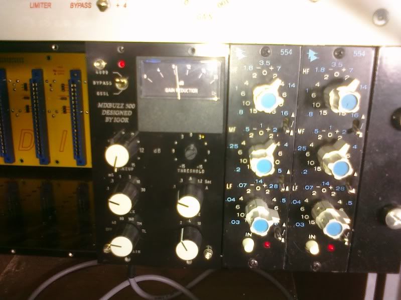
it's alive  ALIVE!!!!!

CIMG0017.jpg


all mode work just one thing , the ratio  on 4000 mode compress even ifthere is no sound , the meter give more than 8 of db rection like on my picture , perhaps i cause i've not put the TR TRimmer or pehaps one error.

and don't forget to link the 3 point on the side of switch on off on if not the relay could not work and the unit stay in bypass

 
Does any one know what chip to use to give me the biggest tonal difference from a Roll Music Super Stereo?  I have one of those and love it and would like to have a mixbuzz that is different tonally and such.  Thanks.  Another great project by Igor.
 
Stereokillah, well done! 
Mike, thanks for the info.  I didn't know those companies had Canadian distribution. 
I'm wondering if this meter from hairball is a direct replacement for the AL19 used in this build:
http://hairballaudio.com/shop/product_info.php?cPath=25&products_id=61

Anybody know?
 
Thank you every body.
"dbeeson" I'm wondering if this meter from hairball is a direct replacement for the AL19 used in this build:
  yes this model have the exact size and fsp  like AL19 it's the substitute

What are people using for sockets for the 2181 chips?
you could use the half of Tl074 socket, i used socket line 40 pin that should be cut by 8 pin i found it on ebay but don't rembember where.
 
after some test i found other problem but not the error, the output signal is like limiteur, with the makeup or with source the sound can't be more than -14db peak on my protools.

 
Stereokillah: you FAST!!!!!! Congrats, and let's see how we fix it together.

in fact with the schema should be

Sidechain = RV1= IC11a = pin1

Audio = SYM = IC11b = pin7

Thanx for pointing to this. My mistake. Fixed.

I updated third post of this thread.

Now, little by little.
I thought pictures shows it clear that unit should be tested outside the rack.

all mode work just one thing , the ratio on 4000 mode compress even ifthere is no sound ,
the meter give more than 8 of db rection like on my picture ,
perhaps i cause i've not put the TR TRimmer or pehaps one error.
I think there's an error here.
Let's do next. Take the unit outside the rack and connect it with Molex connectors,
in/out and power supply. Power supply should be connected to both audio and control pcb's.

Or, disassemble it and put audio pcb's into slots and use longer wires to front panel.

First thing we do, is check audio passing at unity gain when makeup at zero.
Than, the rest.

Check CTL1 and SC1 goes to left, CTL2 and SC2 goes to right.
Check if there's no mess with power connection to front PCB.

and don't forget to link the 3 point on the side of switch on off on if not the relay could not work and the unit stay in bypass
That's right :)
This jumper is for people who will use the unit in GSSL or Gyraf mode only,
but... just put a solder joint here to have both options.

after some test i found other problem but not the error, the output signal is like limiteur, with the makeup or with source the sound can't be more than -14db peak on my protools.
Something is wrong. Let's check audio for unity gain first.
What VCA's are used? Maybe, wrong resistor somewhere?
 
hi igor,

thanks for congrats without my wife in house i have so much time to do what i want.

Quote
all mode work just one thing , the ratio on 4000 mode compress even ifthere is no sound ,
the meter give more than 8 of db rection like on my picture ,
perhaps i cause i've not put the TR TRimmer or pehaps one error.
I think there's an error here.
Let's do next. Take the unit outside the rack and connect it with Molex connectors,
in/out and power supply. Power supply should be connected to both audio and control pcb's.


Or, disassemble it and put audio pcb's into slots and use longer wires to front panel.

First thing we do, is check audio passing at unity gain when makeup at zero.
Than, the rest.

Check CTL1 and SC1 goes to left, CTL2 and SC2 goes to right.
Check if there's no mess with power connection to front PCB.

yes i found the error this morning it was one diode on controle board in a bad sens "RESOLVED"

before pput it in the box i've calibrated it but now is disassambled and i test it with 15pins edge connector and prototyping PCBs

this is what i did exactly

-CBP 100nf AVX

- relay coil resistance is 360ohm well tbd is 60ohm 1/2

- VCA dbx 202X R4=3k74, R3=4k99, R100=909R + timmer  ( 5532 pin7 is at 0.0mV )

- dip tl074 5532 1646 1246 tl072

- VCA sidechain THAT2180C without trimmer

- trimmer sidechain filter changed to 5k1 pin 1 and 3

- no trimmer on TR TRM

during this message i found one thing perhpas should help us : on the bom you said R6 3k74 but on the thread you said R4 perhaps and i put 3k74 on R6 and R4 but R4 need to be 0R right?


once again an aclamation for Inspector COLOMBO. ;D ;D ;D ;D ;D ;D ;D ;D ;D
 
I understand you. Hope the things will be better.

yes i found the error this morning it was one diode on controle board in a bad sens "RESOLVED"

Tell us which one. Does the unit works now?

-CBP 100nf AVX
Or X7R, etc. 47nf...0.22uF will do the job.

- relay coil resistance is 360ohm well tbd is 60ohm 1/2
I used relay's with coil resistance about 1k. Less current, less load for power supply.
Your math is right.

- VCA dbx 202X R4=3k74, R3=4k99, R100=909R + timmer  ( 5532 pin7 is at 0.0mV )

R6=3k74, R3=4k99, R100=909R.
R4 is ferrite bead or jumper.
Killah, many thanx for pointing on this!
I had 2 schematic versions, corrected 3rd post of this thread.

- dip tl074 5532 1646 1246 tl072

- VCA sidechain THAT2180C without trimmer

- trimmer sidechain filter changed to 5k1 pin 1 and 3

- no trimmer on TR TRM
Right

during this message i found one thing perhpas should help us :
on the bom you said R6 3k74 but on the thread you said
R4 perhaps and i put 3k74 on R6 and R4 but R4 need to be 0R right?

R6=3k74, R3=4k99, R100=909R.
R4 is ferrite bead or jumper..


it's 4 am oclock in france i will try the unit this afternoon,

Tell us which one. Does the unit works now?
for the ratio 2 in 4000 mode the error was D8 i I put in the wrong direction, it work fine just still have limiting
Or X7R, etc. 47nf...0.22uF will do the job.
yes it's 100nf X7R not avx

i put ferrite instead of 3k74 on R4 now i think it's fine,

Well need i calibrated it a new time for audio trimmer?
 
Great :) Let's see how we can fix this limiting.
No need to re-calibrate audio trimpots.
Check little by little front pcb, maybe an error here.
Can you explain how does the unit limiting?
 
i think it was caused by the 3K74 in R4 i'll try the unit this afternoon to see.

is limited at -14db peak without or with make up same if i give some gain in the input, the sound can't go up - 14db. and give some saturation
 
ok, the R4 3k74 was the cause of limiting now the unit work nice

related problems:

- on ratio 2 the point of vu meter come to 8, cause of the diode D8 (for 4000 mode) D7 ( for gsll mode)in bad direction
- R34 & R40 burn the TL074 IC7 is in bad direction, change the resistor and the TL074
- SWITCH 3pdt on off on seems don't work, jsut link the three points ratings of the switch

 
Back
Top