MK47 PCB tube mic kit - build thread

GroupDIY Audio Forum

Help Support GroupDIY Audio Forum:

This site may earn a commission from merchant affiliate links, including eBay, Amazon, and others.
As per bobine's post,

Audio
1 = A- (gray) (connects to pin 3 of XLR at the power supply)
2 = A+ (white) (to pin 2 of XLR at the PS)
Center pin = audio ground (green)  (to pin 1 of XLR)

Power
3 = B- (black [blue in the cable])
4 empty
5 = B+ (red)

Pattern
6 = P (yellow)

Shield to the chassis.

Your six wires and shield should be fine.

Cheers,
--
Don
 
JW said:
Don,
What is the difference between B- and "audio ground?"

Nothing really.  They both ultimately get connected to the same place; that is, ground.  I attached the audio ground to the B- pad/ground plane in the mic and then ran it to pin 1 in the XLR connector back at the power supply.  My mic has ZERO hum and works flawlessly.

Cheers,
--
Don
 
Okay, just wanted to let you guys know. Try not to use Canare Star Quad cable for this application. I was using a 6 meter cable (20ft.)
and was getting horrible RF interference. I even jerry-rigged a separate ground wire to see if the problem was related to running the current through the shield as speculated earlier.

I finally found in my cable box a 10 ft. strand of Gotham GAC-7 (lucky! I forgot I had it) Problem solved. Albeit, it could be the cable length itself, but a 20ft. tube mic cable shouldn't be a problem, and with star quad it was.

Should've listened to you a long time ago Max!
 
Just about done with the PSU. Used 3-1k1 10 watt power resistors.
It puts the adj pot in the center and they run cooler than the 5 watt.
Looking at the schematic how is the pattern switch wired?
 
Winetree said:
Used 3-1k1 10 watt power resistors.

That's a good idea. I'm about to start my second PS, so I'll try that.

the pattern switch is an SPDT that either puts the relay in the circuit or connects the 12K dummy load.
 
Hey all!

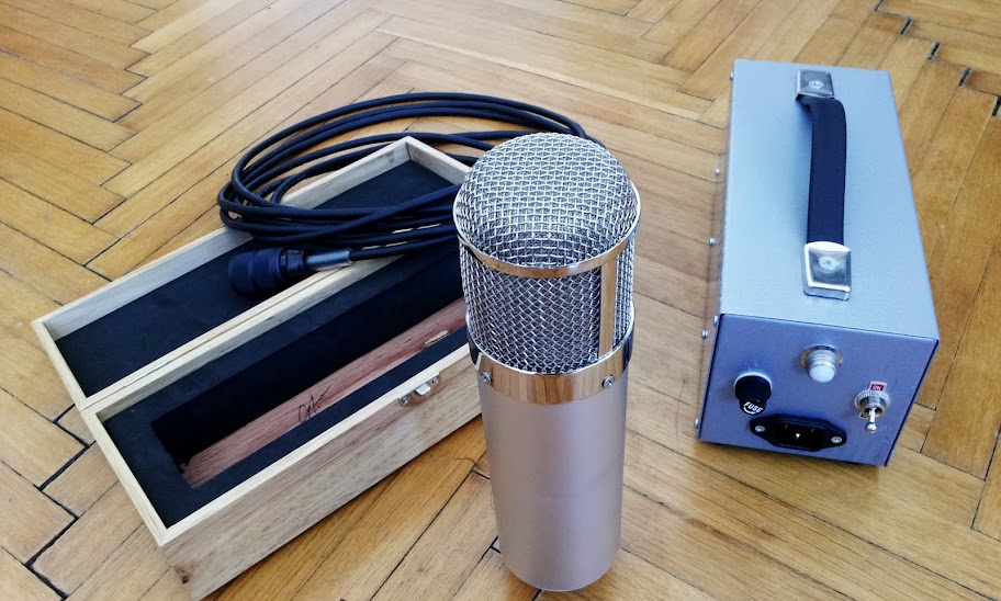
I finished my MK47!  Sounds incredible! Really, really good. I´m very happy and satisfied! Thank you Max, Skylar, Grandmaster and everybody!!!!!!
the only thing not working yet is the pattern switch, gotta check that out....

here´s a pic of my finished set:
C360_2011-05-24%2B12-15-46.jpg

 
thanks! the box is from the beesneez group buy. I don´t know if he sells them seperately...
 
Winetree said:
Hooked up the mics to the power supply. No load, no glow, no go.
Read the earlier posts. Looks like I'll be lookin for tubes.

Do you have the correct voltages from the power supply when the mic isn't connected?  It's hard to believe that both tubes have inoperative heaters. 

Cheers,
--
Don
 
Yes, many times. 105vdc loaded, 292 vdc unloaded.
First mic loads and adjusts to 105vdc. Pluged in it just hums, no audio.
Second doesn't even load power supply. 292vdc at PSB.
Pulled tubes can only check pin resistance. Ordered 10 NOS tubes.
 
Is the power getting to the mic on the correct wires?  Do you have power at the heater pins?  Someone had a similar problem a few pages back and tracked it down.
 
Yes,
Concerning your problem with the high voltage, (292V) I was getting around that voltage and it turned out it was a bad tube, not loading the circuit.

Funny, I actually had the same problem as with your other mic as well. Adjustable to 105V but no sound other than hum/hiss. This problem turned out to be a bad cap (10nF cap.) I had partially melted it with my soldering iron without noticing, though I imagine your problem in this regard could be one of a number of things. Try resoldering the 90 degree tabs. And look real close at the high impedance area.
 
kante1603 said:
0dbfs said:
Awww 680 grams. She's very cute.

And how have you named her?

Hi,
not decided yet because I don´t know if it is male or female maybe "BLU47"? :D :D :D

Udo.

looks very good mate (although photos are now down!)
i have also bought a t bone 700 for this purpose. do you have any hints/particular issues i should look out for? Did you use the psu case that comes with the t bone?
 
Back
Top