


Alright. After some time fiddling around with Cubase or the volume control of my audio interface i decided it's time to get a decent monitor controller. Unfortunately i got kinda addicted to diy and decided only to buy things i couldn't build myself. This year I'm about to get my masters degree in electrical engineering, but as i went the MATLAB/Programming/Digital signal processing way straight to working in the electro acoustics business now, my knowledge in analog circuit design is practically non-existing.
I can read schematics, know basic things like R=U/I and could even calculate circuits with transistors or op-amps if i breed long enough over it.
Nevertheless my goal is:
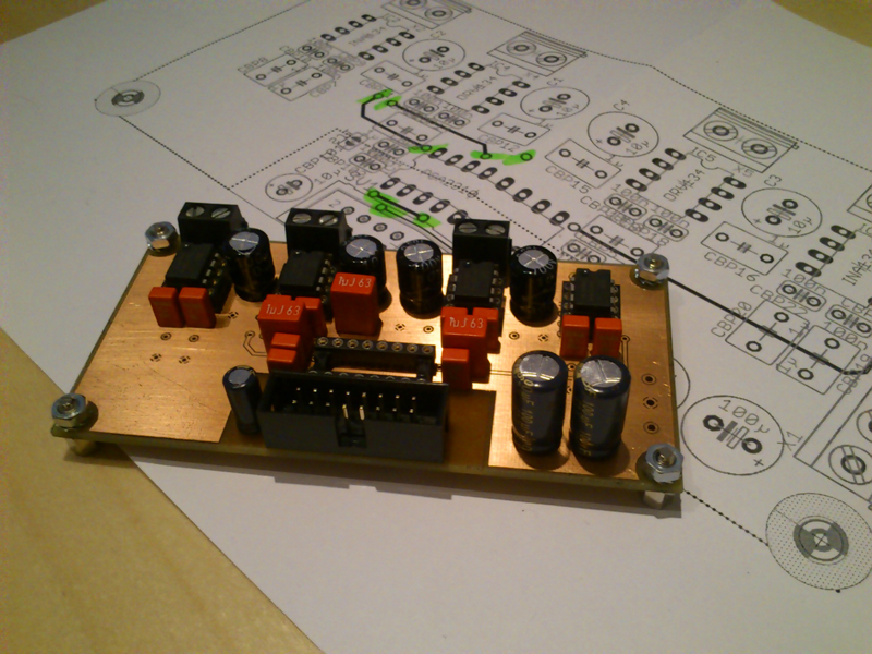
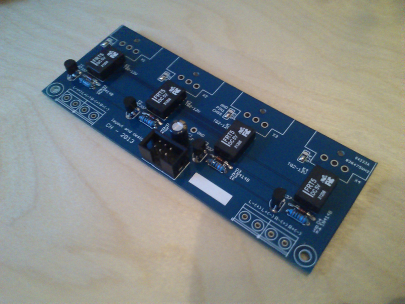
- To build a passive monitor controller based on the signal path of Igors CRM (I hope this is ok :-[ )
- Add a Headphone amp
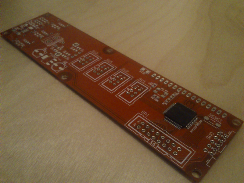
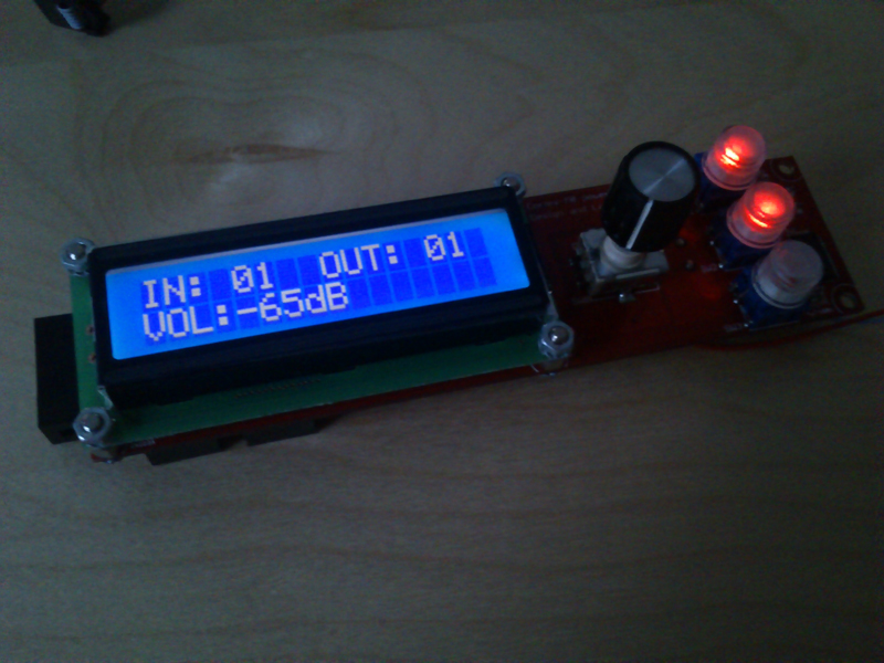
- Design a control unit based on a microcontroller like Arduino
- As some Arduinos offer a USB connection i'd like to design a GUI for the controller, so that it can even be used without the control unit
So if i don't mess it up and some of you guys are interested in this kind of project i'd love to share board layouts and schematics with you.
But no thread without questions 8) so here it comes: To integrate the monitor controller it's necessary to grab the audio signal from the signal path. Can i just wire the debalancing stage of the amplifier unit in parallel to the signal path before the damping resistors, or is it necessary to use things like voltage follower circuits?
Thanks a lot
tobi
I can read schematics, know basic things like R=U/I and could even calculate circuits with transistors or op-amps if i breed long enough over it.
Nevertheless my goal is:
- To build a passive monitor controller based on the signal path of Igors CRM (I hope this is ok :-[ )
- Add a Headphone amp
- Design a control unit based on a microcontroller like Arduino
- As some Arduinos offer a USB connection i'd like to design a GUI for the controller, so that it can even be used without the control unit
So if i don't mess it up and some of you guys are interested in this kind of project i'd love to share board layouts and schematics with you.
But no thread without questions 8) so here it comes: To integrate the monitor controller it's necessary to grab the audio signal from the signal path. Can i just wire the debalancing stage of the amplifier unit in parallel to the signal path before the damping resistors, or is it necessary to use things like voltage follower circuits?
Thanks a lot
tobi
")