Motown Direct Amplifier-inspired Preamp?

GroupDIY Audio Forum

Help Support GroupDIY Audio Forum:

This site may earn a commission from merchant affiliate links, including eBay, Amazon, and others.
That's right, sheet rocked and painted with shelac. I believe they also had an EMT 140 plate.

Well so much for offering a potentially destitute museum owner money for reverse engineering,

"In October 2016, the museum announced a $50-million-dollar expansion plan in order to create space for interactive exhibits and recording studios.] Since the announcement, the museum has received donations from organizations like The Kresge Foundation, the AARP, and the W.K. Kellogg Foundation to help with both the expansion as well as community programming."

Quick thumb if that is Robert White, could be the Firebird in the neck position, sounds like a pick,


Last edited:
I think I remember reading that the one stage was 4 db Dave P - I think you are right. I was in contact with some Gordy last year - I will ask them on another site - maybe we get lucky... I think Silvertone on GS bought a DI Motown preamp(s) a ways back - will check
 
Yes that does sound different .

They use to split her voice, one channel was normal. The second channel was sent through a filter to extract the upper freqs of the hi end, then they would boost the crap out of it and combine it with the normal channel. That's why she had that shimmer on her vocs.

Years later somebody put that idea in a box and called it the aural exciter, although I think the method used was a bit different.

They had tricks for trying to make AM radio sound hi fi.
 
Would readers be interested if I did a full research on the project as if I was going to make it?
There is some tech stuff that needs to be further explored I think.
[Would readers be interested if I did a full research on the project as if I was going to make it?] -- I personally would merely enjoy creating and designing all of the sheet-metal and PCB-designs. So.....whenever you are able to come up with a completed schematic, I would just get a kick out of turning the schematic into a physical reality so others would be able to actually build it!!!

/
 
Well were gonna need a power supply first,

What about running the preamp tubes at about 250, the driver at 300 and the cathode follower at around 325 - 350?

Don't believe this is a White follower as the reissue uses 1 tube. So a MEQ schemo would work with the grid bias fixed by the 12AX7, (I think the Sweetwater specs said 12AT7 but those are too noisy for this project)

The HS 52 does not have a big enough core for this job, and nobody makes this F lams anyway, so 50 EI would be a better choice, wound Triad style, (sec PRI sec) lap 1 core since we have a cap feeding the primary. No taps needed,

Parallel the first tube and we still have two stages left to make up for the vol control and neg fb.

RCA 7025's and a RCA 6BX7 for authenticity,

7025 current demand will be about 6 ma, 6BX7 worst case would be 50 ma so we need about 60 ma on the pwr xfmr.

A few plate and cathode resistors, coupling caps, don't really need a pwr supply choke with a good pi filter,

NFB values and tone shaping can be determined on the bread board.

Heck, since we have an unused 6BX7 section, why not go stereo? Don't parallel the first stage and you only need one more tube socket for a 7025, pwr xfmr will have to be a bit bigger, and two opt's.
 
Last edited:
Where did the idea to use a 6BX7 come from? I know it has been used as an audio amplifier but it was originally intended for a TV frame oscillator and amplifier.
I think it was used for its power delivery and I also believe it was doubled-up to increase the gm and lower the output impedance.
It would not have been good engineering to use three for the five channels because it would have left one section spare (double triode), so they doubled up to obtain a high gm etc. at a low current operating point. Imagine the current drain of four 6BX7 at 42- 80mA each which is the spec for the quoted mu of 10 and gm of 7.6.

I will draw some graphs later to check this out.
best
DaveP
 
Just wanted to chime in, nice that this is picking up traction again. All the original research plus any schematics that I drew up were lost when a hard drive went down a couple of years ago. That, paired with a few house moves and lots of life getting in the way etc, meant that despite having *most* of the parts to start putting something together, I didn't get around to it. All those parts including a chassis, power supply transformer, output transformer, VU meter are still sat there waiting.

The last schematic I remember drawing up was a mix of MB-1 and MEQ-5 with 1x 12AX7 and 1x 6V6. Be interesting to see how this develops!

Cheers
 
One thing I like about the Motown stuff is they divided up the audio band into distinct sections. Then they filled in the sections with various instruments in a way that did not overlap. Not like today where all 56 faders are loaded with junk that creates a wall of crap.

The best mix is a good arrangement. This is a thing I drill into every single student I see.
 
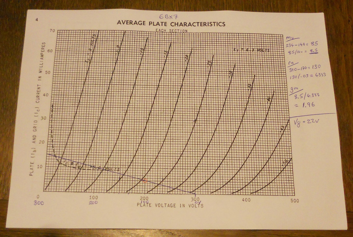
OK, I have worked out the figures for the 6BX7-GT using a B+ of 300V. I have noted from earlier posts that the total current using both triodes paired should be 10mA, this means that I had to work out the cathode follower for a current of 5mA/triode. Although the maximum heater to cathode voltage is given as 200V, I have worked it out for 100V to be on the safe side.
In the chart below, the voltages are reversed for cathode follower connection.


5mA gives a mu of 8.5 instead of 10 and a gm of 1.96 instead of 7.6, the rp is 4.3K instead of 1.3K, (published figures)
Doubled up we have a 6BX7 CF with mu 8.5, gm 3.92 and rp of 2.15k, this might indicate the reason why the tube was doubled up.

For comparison I have calculated the figures for a triode wired 6V6 under the same conditions:- mu=8, gm=2 and rp=4K.
The paired 6BX7 has double the spec of the 6V6 at 10mA, would this matter?

This is what happens to the amps output impedance. If we assume NFB of 20dB, then the output Z of the 6BX7 would be
2150 ohms/10=215ohms/25 (OPT)=8.6ohms, this could easily drive a 300 ohm load.
Equally the 6V6 would give an output Z of 16ohms.

The gain of the 6BX7 CF would be 17/18 = 0.94 and the 6V6 would be 8/9 = 0.89.
best
DaveP
 
Last edited:
I think when you parallel tubes mu stays the same. gm doubles and rp halves so mu = gm x rp is unchanged.

As we know, output impedance is no indicator of drive capability which is determine primarily by quiescent current. 10mA may be enough but it might be a little on the light side. It depend how much headroom we want.

Cheers

Ian
 
so here is an MEQ 5 with an extra gain stage,

gm specs

6V6GT 3600 mhos
12BH7a 3100 mhos
6BX7-GT 7600 mhos
 

Attachments

  • m1.JPG
    m1.JPG
    283.4 KB
Last edited:
The main gain stage of that is used in several Pultec products. The MB-1 mic pre for example replaces the 6BX6 with and ECC88 with its triodes wired in parallel. The really good thing about this circuit is the dc coupling of the negative feedback to the first stage. This means there is only one zero in the loop so it is unconditionally stable at LF and the 10pF adds a dominant pole at HF. Those guys knew their stuff. This was the inspiration for my own designs.

Looks like the 6BX6 is biased at about 9mA.

Cheers

Ian
 
Back
Top