Motown Direct Amplifier-inspired Preamp?

GroupDIY Audio Forum

Help Support GroupDIY Audio Forum:

This site may earn a commission from merchant affiliate links, including eBay, Amazon, and others.
FWIW, this page

There's also a top of chassis pic (I've brightened it since the can cap is difficult to make out in the original) :
Interesting take on the picture, sort of new perspective ... which makes me realise this is built on a PCB ... Makes sens from a manufacturing process point of view, but it's a bit sad, IMO. A cute little design likes this screams PTP to me :)
 
Last edited:
Dave's circuit is looking a lot better since i took out the Neve isolation transformer i was using to drive the input, flat to 100 K with no phase shift! My circuit starts to shift at about 10 K Hz, is flat to about 20 K Hz,

the square wave problem also disappeared after removal of the offending xfmr.

overall gain with the OPT strapped for 600 ohms is about 46.

that circuit i built has worse specs than Dave's but it clips a little nicer.

amps with feedback tend to clip in a harsh manner, but since they have more headroom, the clipping will probably never take place.
 

Attachments

  • sc2.JPG
    sc2.JPG
    239.9 KB
Last edited:
Thanks Brian!
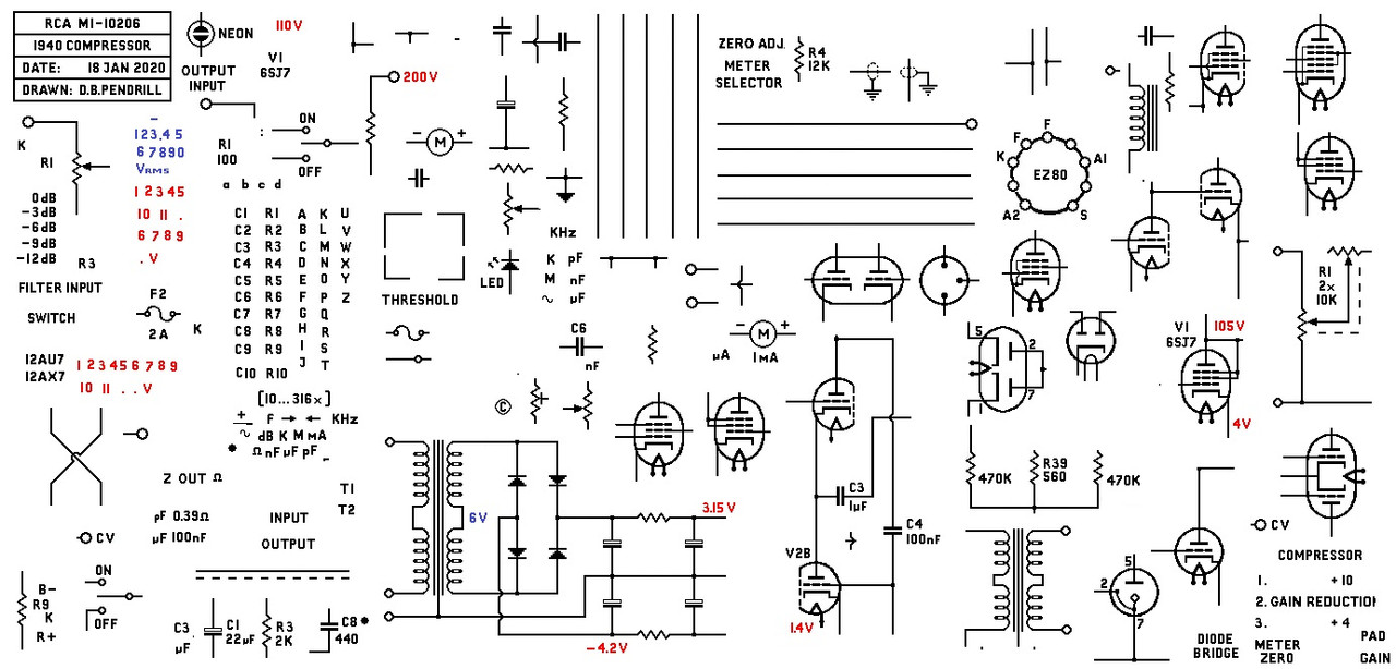
There is no app as such, you might notice the similarity to the original LA-2 schematic?
When I made an LA-2 back in 2008, I copied the schematic into MS Paint and after tidying it up, I have been using it ever since.

I just copy and paste, its quite therapeutic!
best
DaveP
 
There is no app as such, you might notice the similarity to the original LA-2 schematic?
When I made an LA-2 back in 2008, I copied the schematic into MS Paint and after tidying it up, I have been using it ever since.
Same technique I was using for the schematics at the start of the thread (albeit with Photoshop and a Pultec diagram) and I agree, there's just something relaxing about it!
 
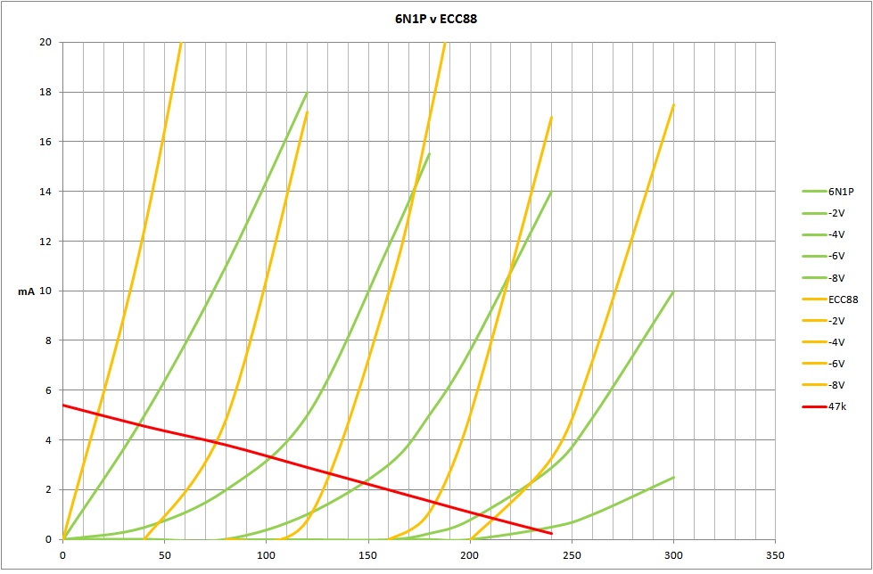
CJ has made the first practical version of this circuit with the tubes he had "in his sock drawer", being a 6N1P.
I made this combined chart to show the difference in the working point when using the 6N1P instead of the ECC88.

The green traces are the 6N1P @ OV, -2V, -4V, -6V and -8V, the orange traces are the same voltages for the ECC88.
The red line is the 47k load line.
The 6N1P has very curved lines down there compared to the ECC88. I think it is also more linear around the -4V working point.
This may make it more transparent, but maybe the 6N1P may have more "tone"?
best
DaveP
 
Last edited:

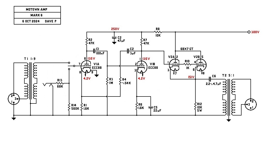
CDave do you think I should change that 10 K resistor on the cathode to get a voltage closer to your schematic?
I think around 150V is a safe cathode voltage for long life, but I guess its the plate voltage of the triode feeding it that is controlling the cathode voltage, that needs to be about 135V to give 150V at the cathode. Maybe lower the B+ for the final triode?
best
DaveP
 
here are some new voltages after the 6N1P swap for the 12AX7a and some adjustments to the pwr supply,
input level was jacked up to 800 mx P-P, starts to clip at 1.5 V-RMS input>
 

Attachments

  • dave pre.jpg
    dave pre.jpg
    102.2 KB
Last edited:
did some side by side tests,

showing the attenuation and shift of my circuit compared to Dave's for a 800 mv P-P sine wave at various frequencies>
 

Attachments

  • s10k.JPG
    s10k.JPG
    245.8 KB
  • s15k.JPG
    s15k.JPG
    276.7 KB
  • s20k.JPG
    s20k.JPG
    253.1 KB
  • s30k.JPG
    s30k.JPG
    261.2 KB
  • s40k.JPG
    s40k.JPG
    274.2 KB
  • s60k.JPG
    s60k.JPG
    291.8 KB
  • s500k.JPG
    s500k.JPG
    224.5 KB
square wave tests, this is on the primary side of the output xfmr, notice the crisp corners on Dave's circuit at 1 KC , no doubt due to the NFB being applied to the first stage,
 

Attachments

  • sq1k.JPG
    sq1k.JPG
    344.1 KB
  • sq10k.JPG
    sq10k.JPG
    246.9 KB
  • sq100k.JPG
    sq100k.JPG
    228.9 KB
  • sq500k.JPG
    sq500k.JPG
    248.8 KB
here's where things get interesting, to me at least,

sq wave shots on the secondary of the output xfmr,

Dave's circuit has that transformer ringing a lot, is this because of the better sq wave response producing more harmonics or something? i doubt the transformers are different, they look like they came from the same lot,

remember the "sharper corners" comment up one post? i bet that is the reason for the ringing.

so a preamp that is lo-fi, with no NFB might be better when it comes to ringing in the transformer?
 

Attachments

  • xfmr1k.JPG
    xfmr1k.JPG
    248.3 KB
  • xfmr10k.JPG
    xfmr10k.JPG
    255.3 KB
  • xfmr100 kc.JPG
    xfmr100 kc.JPG
    323.5 KB
  • xfmr500 k.JPG
    xfmr500 k.JPG
    273.3 KB
clip test, sine wave in at 1 KC, 1,2,3 and 5 v rms into the input jacks, out of sequence,

going to take it home for another listening test,
 

Attachments

  • c3.JPG
    c3.JPG
    305.6 KB
  • c1.JPG
    c1.JPG
    284 KB
  • c2.JPG
    c2.JPG
    258.1 KB
  • c4.JPG
    c4.JPG
    285.7 KB
Back
Top