My GSSL - finally finished

GroupDIY Audio Forum

Help Support GroupDIY Audio Forum:

This site may earn a commission from merchant affiliate links, including eBay, Amazon, and others.
[quote author="Purusha"]Peter, can you recommend a good spot where to take the voltage from for the thrusty?

Would + - 15V be also OK? I think it would be just the same.[/quote]
Yup.

Also, you might want to consider some type of heatsink for the +/-15V regulators. In a standard GSSL, they run a little warm, but this isn't a big deal. Adding two more 5532 will draw a little more (don't know how much off hand). So a small heatsink isn't a bad idea (but make sure they don't touch), or maybe case mounting this is a good idea.

It might not be necessary, but just a thought.
 
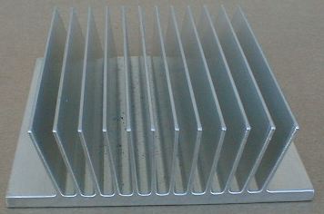
a heatsink is any thermal dissipation thing
like this one:
heatsink-undrilled.JPG
 
Take a look at the picture for reference:

http://members.cox.net/capstanrecording/DIY/G1176/G1176_PCB.JPG

It's that black thing mounted directly to the regulator. Ever notice the hole in the heatsink (or more general in a TO-220 package transistor)... that's for a heatsink.

But in your case, you have the +15 and -15 regulators right next to one another. So be careful because you don't want the heatsinks to touch, unless you positive they're isolated from the regulator. I've seen picutures of some people mounting the regulators to the cases (isolated of course) and running wires to the PCB.

But the heatsink might not be necessary. Perhaps you can just build it without and see how hot the regulator gets. If it gets so hot you can't keep your finger on it, then use a heatsink.
 
Thanks Greg,

I'll do that. Let's see. I will also need the extra +-12V for relays for the true bypass. If needed I will move and solder the regulators on the euro board where my Thrusty is right now and use some extra heatsink coolers.
 
I have a question regarding those two 47K summing resistors on the main PCB. I know when the filter is used than those two are to be removed. OK, here my dillema starts, in the thread about calibrating the ratio and threshold there are suggestions to replace those 47Ks to 120K resistors, but now they are not there anymore so which resistors are now taking their place on the filter?

I also don't know what are those trim pots on both filters for?

Does adding the HP filters change the ratio or threshold behavior?
 
I also don't know what are those trim pots on both filters for?

For setting the threshold to your taste. Originally the hp filter was unity gain, but in the design process of the filter pcb it was made variable gain.

Does adding the HP filters change the ratio or threshold behavior?

yes, that is what the trim pot is for: getting your threshold level right. This has nothing to do with ratio adjustment, btw.
 
You mean VR2 & VR3 in this schematic ?
http://home.hetnet.nl/~chickennerdpig/FILES/API/API-Thrust-HPF-circuit_20060310.pdf

Please do read those notes in that schematic, all info was there already.
Note *1*.

Yes, VR2 and VR3. I have to check your pdf file again. Sometimes I can be a little sloppy ...

The main thing to remember is this: You need to be sure that your VCA is seeing no more than 120mV or your ratio will be way off. (I.e. you are seeing 260mV at the Ec pin)

Which pin of the VCA should I meassure?
 
I am new to this DIY process so I am a little hesitating when things come to measurements. Just to be sure, the pin 1. starts on the marked VCA side or on the opposite side? You know one side of the VCA is marked on the top to know which side is right when you put them in. I checked the pdf for 2181 and the pin 3 is the Ec as you mentioned.

Should I be passing the audio signal through when measuring or not necessary?
 
Final check if I understood everything before I do this.

When you say "set the ratio to 20:1" you mean 10:1?

Regarding the measuring process, the + (red) cable from the volt meter goes to the pin 3 and the other one goes to the XLR ground connection in the input or output section, yes? Maybe this question sounds a little funny for experts but anyway, better to ask than to be sorry later.
 
OK, here is what I got

Threshold fully CCW = 139.4 mV
Threshold 12 o'clock = 40 mV
Threshold fully CW = 0.4 mV

The VCA next to the one I measured had up to 0.2 mV difference.

Is this normal?
 
METER CALIBRATION

Just experienced another surprise... when doing meter calibration or at least tried to calibrate it :green:

1) First thing what I noticed was that when sending 1KHz at 0dB through G-SSL it came back -5.8dB. Is this normal?
BTW I changed the 15K to 27K.

2) OK, than I matched the gain with makeup pot to get back the unity gain 0dB from the G-SSL. Just to mention I replaced the 2K resistor with the 4K7 trimpot for better meter adjustments. Than I turned the threshold pot CCW so I could read 10dB GR on the meter. But the actual GR on my DAW was showing only -4.2dB although the trimpot was at the max resistance 4.7K. If I am right than around 10K of resistance would bring my meter to the proper values to get the 10dB meter scale working. IS THIS NORMAL?

Description: METER, EDGE INDICATING 100UA; Accuracy:+/-20%; Depth, Meter Movement FSD:0-100µA; Resistance, coil:1750R;

When I bought this meters I followed my friend's advice coz I didn't know a thing about what I need and what were the values needed. I hope this are usable. I paid a lot of money for 12 meters. 100uA = 0.1mA? Am I screwed or can this be adjusted with more resistance?
 
If your threshold was fully clockwsise and sending in 1.23VAC since, then this is definitely NOT normal.

The 2K resistor will vary depending on your meter. Since you're using a 100uA, you need to shunt it with a resistor. If you didn't already do this, check the schematic I think it's 330R. This is probably why your resistance is so high.
 

Latest posts

Back
Top