You are using an out of date browser. It may not display this or other websites correctly.
You should upgrade or use an alternative browser.
You should upgrade or use an alternative browser.
neumann v475 pimping ...
- Thread starter [silent:arts]
- Start date
Help Support GroupDIY Audio Forum:
This site may earn a commission from merchant affiliate
links, including eBay, Amazon, and others.
going to be working on a V475-2B that I bought years ago soon and will probably report in here if I have issues lol. measured the Harting connector pinout for 0v / ground continuity and here's what I ended up with, in case this is useful to anyone.
also attached higher res V475-2B schematic and V475-2A service manual (original German, searchable thanks to Acrobat and then a messy Google Translated version to English... you need to copy-and-paste the text out of it)
CONNECTION NOTES:
also attached higher res V475-2B schematic and V475-2A service manual (original German, searchable thanks to Acrobat and then a messy Google Translated version to English... you need to copy-and-paste the text out of it)
CONNECTION NOTES:
- Channel 1 power supply "0V" (pins C14 and C16) do not share continuity with Channel 2 power supply "0V" pins C18 and C20
- +24V input pins for Channel 1 (pins A14 and A16) do not share continuity with +24V input pins for Channel 2 (pins A18 and A20). Any reason for this?
- Channel 1 "0V" ref does not connect to Chassis Ground / earth, BUT the Channel 2 "0V" ref does connect to Chassis Ground: all metal bolt holes and also the metal plate that runs down the middle of the card.
- ALL Channel 1 (input and output signal AND power supply) "0V" pins share continuity with each other. This "0V" ref is also tied to the transformer shield on Channel 1.
- Ch.1 "0V" pins sharing continuity are A6, A10, C6, C10, C14, and C16.
- ALL Channel 2 (input and output signal AND power supply) "0V" pins share continuity with each other. This "0V" ref is also tied to the transformer shield on Channel 2.
- As mentioned, all Channel 2 "0V" connections are also tied to Chassis Ground.
- Ch.2 "0V" pins sharing continuity are A24, A28, C18, C20, C24, and C28.
Attachments
Last edited:
Hello,
I am interested into building some summing busses with these Neumanns 475 2c for my API modules for the returns effects.
I would like to know where could I find the built in recommendations in order to select the value of the input resistors for a 16 channels inputs for exemple. And Principally, I am interested in order to get everything interesting to build this summing.
Could you please tell me where to find these informations?
Best Regards,
Francois
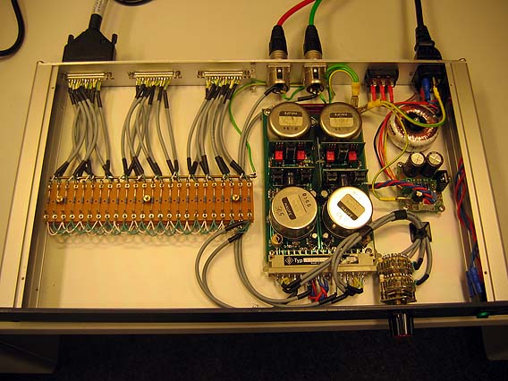
Hi Kante1603, I notice you are from Munich. Well, I work in Munich and live "not that far". I am interested to build 2 summing to create busses for my home built "custom console". I am interested to know how to define the resistor value for a 16 inputs solution... Could you please help me? Grüß, Francois…and another one,here you can see the resistors directly mounted on the SIEMENS plugs,the relays board etc.
Hi, may be an API 2520?Hi Steph,
I don't see any advantage in replacing the op amps.
the V475 is great like it is!
it won't be better with other op amps.
[silent:arts]
Well-known member
Hi Francois, the recommended standard value for the input resistors RE is 2 x 5,11kΩ together with RG = 2 x 13kΩ for 0dB gain. The number of input channels doesn't matter.
deleteduser
Active member
WOW! WOW! Looks incredible. Next time you might as well use 1 Watt resistors cause why not..? (It makes a slight but noticeable difference.)
Best
Saul
Edit. Oh Silent Arts!! Hello. I have your name on a circuit card! My friend gave me a stereo LA-2a card or something and power transformer? I guess I need to hook it all up, its all pretty obvious or is there some sort of paperwork that goes with it? Thanks!
There are 108 pages of digital paperwork in the D-LA2A Support Thread.WOW! WOW! Looks incredible. Next time you might as well use 1 Watt resistors cause why not..? (It makes a slight but noticeable difference.)
Best
Saul
Edit. Oh Silent Arts!! Hello. I have your name on a circuit card! My friend gave me a stereo LA-2a card or something and power transformer? I guess I need to hook it all up, its all pretty obvious or is there some sort of paperwork that goes with it? Thanks!
Similar threads
- Replies
- 0
- Views
- 382
- Replies
- 0
- Views
- 448
- Replies
- 2
- Views
- 603
- Replies
- 5
- Views
- 1K


