Neumann Vintage U87 Clone : Build Thread.

GroupDIY Audio Forum

Help Support GroupDIY Audio Forum:

This site may earn a commission from merchant affiliate links, including eBay, Amazon, and others.
sr1200 said:
you forgot about the part about you separating me from more of my money once those bodies come in... :)

i can put you on a stop list if you wish  ;) :),

Best,
Dan,
 
Just want to register another build. Big thanks to Dany for initiating this insanely great project, and to everyone who posted on the thread - it all helped to make the build smoother.

A number of pics here - https://www.flickr.com/photos/123453231@N02/sets/72157644065907975/

Details
I went for the cheap and popular options - tantalum and styro caps, Cinemag 2480 transformer, mic-parts RK-87 capsule and a MXL 2001a donor.
I started off wanting a body with switches, but the options are quite limited. Thinking about it more, it's actually no big deal opening the mic to change settings. The MXL 2001a body works fine, you need to file down the opening to the head basket to allow for the slightly bigger capsule. The screw holes for the boards line up perfectly which makes for a neat build. I used nail polish remover to take off the gold MXL lettering from the body - you need to rub it quite a bit but it will come off OK.
I used a fet with Idss of 7.7mA, and biased with a multimeter to 10.5V at the drain which seems to work fine in my case.

Mods and experiments
Board mounted switches
I used a NKK SS series slide switch mounted on the pcb for the pad - see pics. This may not be a good idea! They're rated only to 28v. However, the mic won't be powered when the switch is moved, so the usual problems with arcing on contact bounce etc. shouldn't happen. It seems to work OK for now, but time will tell how long the switch lasts - I'll report back.

Two-stage Low Cut
I wanted a less aggresive low cut, so I've made a two stage low cut - see the pics. I used a 3-pin header, the left-most pin is cut off underneath and the bottom of the pin is soldered to one end of the extra resistor. The other 2 pins are soldered in the LC holes as normal - it helps if you mount the adjacent capacitor (C4) slightly to the left. The other end of the extra resistor is soldered to the bottom of R2 as shown. So right-jumper gives standard U87 low cut, and left-jumper gives a gentler low cut.
Choose the value of the extra resistor to taste - I've used 470k for now.

Overall
I only tested the mic using the mic input on my audio interface but it's sounding very good so far. I'll test it on a proper preamp later. As others have said, it does need a lot of gain - I thought it wasn't working at first!
I'm sure this is going to be a great mic, that I use a lot. Compared with stock mics that you could buy for the same money, it's a steal. On top of all that I get the satisfaction of having built it myself - count me happy!


Attachments

  • u87-2.jpg
    u87-2.jpg
    132.6 KB
Hey all,

I'm having trouble getting the bias on my Dany board correct. One of the complete kits from micandmod w/ the 67 capsule. The trimpot seems to stop at 1.44VDC even if i keep turning it up. I'm using the Mulitmeter method of biasing for now. Just thought I would see if anyone has had this issue. In the meantime I'll keep troubleshooting..

Thanks,
 
Hi Karl,

Was going to suggest checking R12 and R13 are in the correct positions, as I made the same mistake on my build, but you got there first.

Regards,

Aleks
 
Hey
I just finished constructing my u87 DIY.
My problem now is that's almost can't here anything, I have to crank my preamp to get a signal.
The only thing that's loud enough are the switches. When I record a signal into my DAW there's almost just noise until I flick between the switches., witch gives big transients. There is a signal and I can hear my own voice but it's very very low and muffled.
It's my first time putting a mic togheter but I think I've done it right and I followed instructions. And I've been treating the capsule with great care.
Please help me identify my problem. 
Peace
 
Jay82 said:
Hey
I just finished constructing my u87 DIY.
...

Congratulations on the build!
I'm no expert, but it'll make it easier for others to help if you can post as much info as possible.
As a first step, put some pics of the boards (both sides) online, and post a link. Try to make the pics as good as possible.
Did you measure the fet before installing it? How did you bias it?
Get a multimeter, probe the dc voltages at the critical points in the circuit. See the earlier posts of this thread for the relevant points to probe.
 
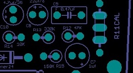
it seems there is a little confusion on the silk screen on R13 and R12 as the print is a little blurry however the resistance value near the component is correct
I have corrected this little issue in the current pcb beeing offered.

but here it is just to make sure everyone can see it properly,
Make sure you did not invert those two component on the board,
check the reference voltage first,

B1 Reference Voltage and Schematic https://cdn.groupbuilder.com/groupdiy/u/39511/58d1402a06c27
B2 Reference Voltage and Schematic http://db.tt/cnwPnNtS


as a start,

58d028199415d.jpg


I've been playing around with my new mic for a few days now.

First impressions - using a 470k resistor for the custom low cut (see above) is just right. It's much closer to a typical low cut. Tonally the mic seems very 'vintage', perhaps a little too much for my taste - I'd like it to sound a little less compressed, and maybe a little more open at the top end.

My experiments with changing various things [component choices were in some part motivated by what I had to hand].

C7 - an obvious place to start. Changed to a 1uF/100v Vishay MKT1813. There isn't much space between the boards, so I mounted it on top of the other components, connecting the other end to TRFO-1. Result: not as radical as some people seem to claim, but it does a lot to alleviate some of the compressed feel to the sound.

C6 - The subject of much debate, some people remove it altogether. I replaced it with a Wima 100pF/100v film cap. But see my Edit 2 below.

C8 - replaced with a Vishay 22uF/50v electrolytic. Added a Wima MKS2 100nF/100v in parallel on the back of the board (fits nicely in the unused holes for R11).

I did these changes as a package - this isn't clever in terms of assessing their effect, but with C6 removed, it's much easier to bend down C10 to get to C8 - otherwise it's really fiddly. Result: the mic seems notably softer and smoother in its tone. The top end is hard to assess because I'm only recording my own (fairly deep) voice, but there seems to be a difference there too. Overall it's definitely more pleasing. Worth doing? YES! [see Edit 2 below]

C4 - I know there's an argument that says this doesn't do anything so just pull it. I'm more persuaded by the school of thought that says increase it so that any phase effects get pushed even lower. I replaced it with a polystyrene 1nF/160v cap. Result: Couldn't hear any difference.

I'm not a producer or sound engineer and this is largely a matter of taste, but it may help someone else thinking about experimenting with component choices.

Edit: Just to be clear, my original build was tants and styros, mic-parts RK87 capsule and Cinemag 2480. All the changes to the sound were quite subtle, it's unmistakably the same mic. I'd say it's very much 'vintage but nicer'. If you want something more radical then experiment with removing C9 - I'm personally not interested in that sort of change. All IMHO of course...

Edit 2: I was definitely too hasty in my assessment of the C6 mod! Listening to the mic today, it introduced a lot of nasty sibilance that I wasn't hearing yesterday. It definitely affects the top end a lot. I just don't have producers' ears so it takes me a while to notice these things! I've done some reading on this, and especially looked at Matador's U87 de-emphasis graph that he posted on another thread. I've experimented with other values, both higher and lower than 220pF. It's interesting to try higher values for a nice dark mic! I've now returned to the stock value using a Wima 220pF FKP2 cap. Having experimented, I think this is the best overall choice; it makes for a balanced mic that's easy to EQ. I'm sure the folks at Neumann knew what they were doing!

Conclusion - I'd definitely recommend trying alternative capacitor types for C7 and C8. For the others I'm less convinced that there's much scope for improvement - not surprising given the pedigree of the design. But most of all: experiment and have fun...
 

Attachments

  • IMG_1069.jpg
    IMG_1069.jpg
    67.7 KB
First impressions - using a 470k resistor for the custom low cut (see above) is just right. It's much closer to a typical low cut. Tonally the mic seems very 'vintage', perhaps a little too much for my taste - I'd like it to sound a little less compressed, and maybe a little more open at the top end.

great stuff thanks for all this info and testing report, this thread wishes more contribution like this one ,
wich capsule have you been using as this will defo impact the way the mic will react with the changes you make.
not really for the low cut thingy but for the overall mic response, all a matter of taste but IMHO and i would say i am not the only one that prefers the vintage sound of a U87i rather the one of the U87Ai wich is much brighter on top and propably a little too harsh for me , the fact is that the lower polarisation voltage is also part of the sound of the vintage 87 also,

Best,
dan,
 
poctop said:
great stuff thanks for all this info and testing report, this thread wishes more contribution like this one
...

Thanks Dan. I added an edit to my post clarifying some things. This mic is so much fun to play with, and it wouldn't be a proper diy project without some experimentation! Your approach to this project is great - it's not a 'kit' - you encourage people to make their own choices, so each build is personal.
Best...
 
this is a great and cheap platform for a U87 Project,

http://www.ebay.com/itm/MXL-2001-Large-Capsule-Diaphragm-Condenser-Microphone-/291132344075?pt=US_Pro_Audio_Microphones&hash=item43c8d7070b

Best,
dAn
 
Hi Guys, I've just received my parts from mouser. What is the best Jfet MA to use? I have the following
6.80ma, 7.13ma, 7.21ma, 8.29ma and 8.61 ma.

Cheers Brad
 
Nyquist said:
Hi Guys, I've just received my parts from mouser. What is the best Jfet MA to use? I have the following
6.80ma, 7.13ma, 7.21ma, 8.29ma and 8.61 ma.

Most people seem to choose something under 10mA. Lower values give higher output, but it's not critical. All of your values will sound good. Pick the middle one if you can't decide!
Enjoy your build!
 
Hi D87 crew.
I found a way cheap donor body, and have some pcbs.
Gonna go ahead and make another one.
Mix things up and no regrets.  Polystyrene caps,
TabF transformer (1st one is peluso txfmr, regular BOM parts)
aaaand.....
I wanna make it cardiod only cause the donor has no switches.
I have a question/ possible request if groupdiy permits.
Would someone recommend what capsule to get for cardioid only,
And anyone wanna draw an amended scheme?
Wild card!  I wanna make it look cool and have a port or something to access or look inside to
jump the pad and lo pass.
I was thinking, what if there were a blue led in there????
So it glows inside??
Wacky?
I'd pm some consulting $ or favors or trade or???
If someone could redraw the scheme.
I'm not skilled enough (obviously)

Take care!
Andy
 
Hello Andy,

no need to redraw the schematics.When you look at them you can clearly see that the switch connects to nothing when in cardioid mode mode,so just leave the switch and corresponding wires out and don't set a jumper there.Done.

For capsule choice......up to you I'd say.You can still use a dual diaphragm type,but no need for seperate backplates anymore......the choice gets bigger now.Or a single dia.-type.Just connect it to the front capsule connections.
The advance of a dual membrane is still that you can now choose which side sounds better to your ears.

For the blue led........what for?As an on/off indicator or to make the the membrane shine blueish?
In any case you must get the supply voltage from your phantom power via a resistor.
Remember blue leds will need a certain amount of current that will easily exceed the current for the whole microphone.You must use low or even ultra-low current types.Red leds normally take the lowest,followed by green,yellow,blue and white....there is a lot of information on the internet.
Be careful with blue types,they often have a very small view angle.Some are like looking right into a laser beam!But who cares as long as it sounds good 8).
(Take care of your eyes,not ears in this case).

Best regards,

Udo.


Thanks Udo :)
Well, I still haven't zeroed in on the image in my mind.  I just think it would be neat if there were some type of glow.  Mostly to impress me when I use it!  I need to figure out what would look cool and i'll show some pics if there's a eureka moment.

Ok, I knew about the unjumpered, just didn't know if there was an additional part/ parts to omit.  I'm downloading the scheme now to see about the led.  I guess glowing red is cool...
It'd be neat if there were a spst push see through swith that were somehow flush with the body and pushing it would activate the cut (or another for pad) and illuminate the led or turn it off???

thanks for the response.
I'm going to take my time on this one and slowly accumulate parts under the cheapskate's guide to nice parts for less $; will have to be patient.  Plus, i'm pledging to finally get a scope and learn to use it (that'll be big!) 
Thank you for the capsule advice, very much appreciated.
Take care!
Andy
 
Hi Andy,
I built my second one of these yesterday - I used the stock capsule in the donor body I had laying around (Golden Age FC1), so it's cardioid only. As Udo says, just get any K67 style capsule and connect the front diaphragm to FD, and the body (backplate) to FBK and you're done. If your donor body already has a capsule in it, try that first.

If you're going to buy a capsule then maybe get one with isolated backplates, then at least you have the option of other patterns. I used jumpers on my builds and it only takes a few seconds to change them.  But if you only want cardioid then pretty much any capsule can sound good if you get a nice one (which isn't always related to cost).

I used electrolytic caps for C8 and C10 and a film cap for C7. I'd certainly urge people to try different types for C7 - I don't like tantalums in the signal path, but that's just me.

As for the LED idea: as Udo said you need to keep a lid on the current that you're drawing. You don't want the mic to draw more than about 10mA in phantom power, which is less than what many LED needs. Even 10mA may be pushing it for some interfaces. It depends how bright you want it - try a lower current (and different LEDs) and see if it will glow to an acceptable level. Pick up 48v from the junction of R18 and R19 - connect a LED to ground from that point. Use a resistor in series with it - start around 5K, but go higher if you can. If you steal too much current from the mic then it will affect the sound. And make sure you post some pics!

Edit: This guy may still have some free ones - http://groupdiy.com/index.php?topic=56232.msg717656#msg717656
 
Back
Top