Neumann W75k passive bandpass inductor values?

GroupDIY Audio Forum

Help Support GroupDIY Audio Forum:

This site may earn a commission from merchant affiliate links, including eBay, Amazon, and others.
Winston O'Boogie said:
Yes in parallel.  With the correct value of termination, there should be negligible effect on your filter.
I haven't looked at your schematic ( perhaps I should 😛) but these sorts of filters are generally defined by the source impedance - which was usually assumed to be 200 ohms in Europe - and that the load would be sufficiently bridging to that impedance.

Edit:. I looked at the schem but couldn't see clearly enough I'm afraid.

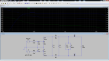
I've attached a picture of my spice model. I have a better copy of the original schematic, so the values are correct. Except for R4 (output termination resistor) which I've put in.  And L3 and L4, the high cut inductors, which are 5.2mH in the original.
Can you maybe explain to me the use of R2 and R3? The two 100 Ohm resistors?

 
Murdock said:
Can you maybe explain to me the use of R2 and R3? The two 100 Ohm resistors?

They look to be part of an initial rf filter.  So, with a 200 ohm source microphone, and the combined 200 ohms of both those resistors, they present somewhat of a defined source z of 400 ohms.  Without them, the source z is completely defined by the particular microphone in use, which is not 100% known.  You can work out the response with the 1st pair of shunt caps using 400 ohms and the usual 1/2piRC.  Wasn't there a choke between the two sets of caps initially?

P.S. thanks for posting your schem.  Also, it was not unknown in some studios during the '50's and '60's for there to be specific filters for specific microphones.  Lots of mics at Abbey Road had their own filters to use, whether that was low cut, or high lift, or whatever was necessary.  So, nothing wrong with adjusting the 100 ohms and 900 ohms shunt to suit whatever you're using it with.
 

Latest posts

Back
Top