You are using an out of date browser. It may not display this or other websites correctly.
You should upgrade or use an alternative browser.
You should upgrade or use an alternative browser.
Neve style 500 series mic pre 1290 1073
- Thread starter onlymeeee
- Start date


Help Support GroupDIY Audio Forum:
This site may earn a commission from merchant affiliate
links, including eBay, Amazon, and others.
MarshallCS
New member
Hi There.
I'm interested in getting a pair of your pre's. I was just curious if there was a way to mod the LowZ switch for pot that gaves a greater range of possibilites of input impedance.
For instance- I'm interested in using these for ribbon microphones. AEA's ribbon mic pre has an input impedence of 18k ohms. Is this even remotely possible with your project, or would it require some heavy modification?
Thanks
Marshall Simmons
Brolik
Well-known member
heyhey,
I've got two of these badboys, been running like steads in the studio for awhile. One fine session, I flipped the phantom on one of them only to receive crackly, clippy sounding audio. It works great with a dynamic mic, but when it comes to phantom, it almost sounds underpowered. Only louder stuff comes through and its really distorted. Any suggestions as to where you might start with troubleshooting. I'm planning to start at the switch and start working my way back along the phantom circuit, but wondering if anyone might have a better idea of how to cut right to the problem.
Thanks!!
desun
Well-known member
So it's only taken me about 3 years to get this far! Having had one of the first deliveries of boards, some of the Mouser parts were out of stock, and I just never got time to finish off this project!
So i've finally populated the boards, but I have a problem-- there's a high pitched whining about 4-5 seconds after power on, and there is only about 0.01V on the can of the 2N3055. I've pulled the 16-24V board and powered that on the bench supply and it seems to be working fine and without any noises. I've also lifted R51 and R56 in turn to try and isolate where the fault is, but to no avail.
Anyone have any ideas where abouts i've ballsed this one up?
Edit: It appears that the +/-16V going to the connector for the DC-DC board is good, and if I use the bench to put 24V on the output of the connector, then I don't get the buzzing, but the case of the 2N3055 went straight to 24V, even though the trimmer was backed right off.
Cheers,
Oli
desun
Well-known member
Err, it appears I may have been a bit daft-- I think the issue was the current limiting that was set too low on my bench supply. Have put the module into an API rack, it now powers up and after 4 seconds the noise stops (when the time delay relays kick in, I guess). And I looked at the instructions a thousand times, but after another look today, I notice it actually says if the 3055 is BELOW 21V then switch off. My awake brain tells me that 24V is not lower than 21V, so it should be ok once i've trimmed it!
Doh!
Doh!
Mrosso
Well-known member
I have a couple Carnhill VTB2168 input transformers from an old group buy. I'd like to stick these into Don 500 series pres. I'm pretty sure these will work, but there is an issue with reversed input polarity (see http://www.groupdiy.com/index.php?topic=21871.msg324359#msg324359). I guess these were made custom, and the polarity got switched at some point on the pins. Can I just put these into the Dons as is, or will this be a problem? Degradation in sound? Can I flip the polarity switch on the front panel to compensate?


![Electronics Soldering Iron Kit, [Upgraded] Soldering Iron 110V 90W LCD Digital Portable Soldering Kit 180-480℃(356-896℉), Welding Tool with ON/OFF Switch, Auto-sleep, Thermostatic Design](https://m.media-amazon.com/images/I/41gRDnlyfJS._SL500_.jpg)


Finished my nv73... Got scared cause of noises and smoke out of the dc-converter pcb at first powerup... but when i re-seated it it seems to work... hope i didnt do damage... Cant seem to get the voltages everyone's getting... when i probe between metalwork and 3055G i get weird readings like 0,045v... but i connected a mic and seems to sound nice and clear... also with a condenser mic and phantom power... gonna have to check more!
jandoste
Well-known member
Hi guys,
I don't know what happened but my N73 doesn't work anymore :'( I got two of them and the second one is awesome!
I changed the 2N3055 but the problem is not fixed! everything is look ok! when I switch phantom switch or in/out potards I hear some clicks but no sound there!
Any advice?
Thanks
I don't know what happened but my N73 doesn't work anymore :'( I got two of them and the second one is awesome!
I changed the 2N3055 but the problem is not fixed! everything is look ok! when I switch phantom switch or in/out potards I hear some clicks but no sound there!
Any advice?
Thanks
culteousness1
Well-known member
Thank you David for making this possible:
Working from first fire up!
Cheers,
Carsten
Working from first fire up!
Cheers,
Carsten
Siegfried Meier
Well-known member
Finished our pre and it sounds great. However, whenever it's racked (screwed) into our Radial SixPack chassis, the audio cuts out - voltage is still there. Something is grounding out or shorting something? Anyone seen this before? This seems odd...
EDIT - I removed the front panel and now it's not doing it anymore...huh? Put the panel back on, it's back...
EDIT THE NEXT MORNING - Ripped apart the entire module, reassembled carefully and now it works fine. Something somewhere must not have been sitting correctly.
EDIT - I removed the front panel and now it's not doing it anymore...huh? Put the panel back on, it's back...
EDIT THE NEXT MORNING - Ripped apart the entire module, reassembled carefully and now it works fine. Something somewhere must not have been sitting correctly.
Unit7
Well-known member
I'm building this too, and the way I read that paragraph, and by looking at other builds I used a shielded cable and connected the lead ends to the Ps and the shield on one side to 0V. The latter only to protect the lead from interference.Toure14 said:So looking at the bottom silk screen and reading that paragraph in red, do I just solder a wire from P to P? I see a gray wire soldered in the picture but it said its not connected so...??
Unit7 said:I'm building this too, and the way I read that paragraph, and by looking at other builds I used a shielded cable and connected the lead ends to the Ps and the shield on one side to 0V. The latter only to protect the lead from interference.Toure14 said:So looking at the bottom silk screen and reading that paragraph in red, do I just solder a wire from P to P? I see a gray wire soldered in the picture but it said its not connected so...??
Yeah I would have used shielded cable but I dont have anything that small. Plus in that paragraph it also said he didnt notice any difference using non-shielded cable so I used silver strand teflon wire.
Also, I bought some Neve style knobs from Classic API and they turned out not to work.
Where is everyone sourcing their NEVE like knobs from?
Unit7
Well-known member
Toure14 said:Unit7 said:I'm building this too, and the way I read that paragraph, and by looking at other builds I used a shielded cable and connected the lead ends to the Ps and the shield on one side to 0V. The latter only to protect the lead from interference.Toure14 said:So looking at the bottom silk screen and reading that paragraph in red, do I just solder a wire from P to P? I see a gray wire soldered in the picture but it said its not connected so...??
Yeah I would have used shielded cable but I dont have anything that small. Plus in that paragraph it also said he didnt notice any difference using non-shielded cable so I used silver strand teflon wire.
Also, I bought some Neve style knobs from Classic API and they turned out not to work.
Where is everyone sourcing their NEVE like knobs from?
Me too bought the new Elma knobs from Jeff and was a bit disappointed that they didn't fit. BUT, the gain knob actually fits and looks great without the nut for the GH switch. I'd like to hear if anyone think it's a bad idea to go ahead without that nut, as it would put more strain on the soldering on the GH?
Otherwise, to compensate for less fastening of the faceplate, I plan to drill four small holes in the corners of the faceplate and L bracket and use nice looking black countersunk screws (just like Neve 10-series modules) to tighten the faceplate.
I also got the grey knob from Jeff for the attenuator pot and found the shaft on the pot too short, so I'll simply just try to find another pot with a longer shaft. Those knobs looks and feels so good I believe it's worth the effort
")
edit: otherwise I found that Don Audio (no not David's Don Classics...) has a good looking knob that you can order without the hole for the fastening screw and then drill the hole yourself and use their screw/steel inlay kit:
Knob: http://www.don-audio.com/Red-Marconi-style-knob-skirted
Screw/steel inlay kit: http://www.don-audio.com/Set-Screw-and-steel-inlay-DIY-kit-for-our-Marconi-Style-knobs
Winetree
Well-known member
I posted awhile back, on one of Jeff's anouncement posts about the knobs, that they didn't work on these pres.
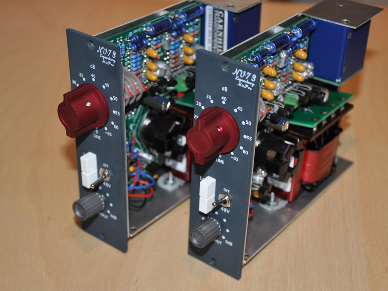
Too bad you guys didn't see it. Chuck D's red knobs worked on mine. You'll also see them in the above picture.
Too bad you guys didn't see it. Chuck D's red knobs worked on mine. You'll also see them in the above picture.
Winetree said:I posted awhile back, on one of Jeff's anouncement posts about the knobs, that they didn't work on these pres.
Too bad you guys didn't see it. Chuck D's red knobs worked on mine. You'll also see them in the above picture.
What doesnt work about them is it the set screws or is it the inside shaft of the knob?
Winetree
Well-known member
The set screws are too close to the top of the knob, making the shafts too short on both knobs.
The hole sizes are correct. Someone suggested redrilling and tapping the holes. Too much work.
The hole sizes are correct. Someone suggested redrilling and tapping the holes. Too much work.
Similar threads
- Replies
- 24
- Views
- 7K
- Replies
- 8
- Views
- 4K