You are using an out of date browser. It may not display this or other websites correctly.
You should upgrade or use an alternative browser.
You should upgrade or use an alternative browser.
Neve style 500 series mic pre 1290 1073
- Thread starter onlymeeee
- Start date


Help Support GroupDIY Audio Forum:
This site may earn a commission from merchant affiliate
links, including eBay, Amazon, and others.
O.K. I think something is wrong with my build. I have turned the trim pot counterclockwise till it clicks.
I connect my multimeter to the 2N3055 and also to my chassis.
I plug it into my API lunchbox. I turn it on and I hear like a fizzing sound like a capacitor is about to blow.
The reading I am getting is about 19-20 volts on my multimeter. It is slowly climbing up but I do not want to wait because the fizzing sound, sounds like its damaging something.
Onlymee, on your calibration instruction, is this what you are saying:
Turn the trimpot counterclockwise.
Plug your multimeter and measure the 2N3055 and the chassis ground when you turn it on.
If it reads below 21 volts turn it off!!
If it reads above 21 volts, adjust the trimpot till the multimeter reads 22volts.
Is this correct?
Does anyone know what could be causing the fizzing sound??
My unit reads below 21 volts, what should I do from here?
Is it the sound (squeal) of the DC-DC converter starting up? This is normal and stops once it's up to voltage. 4 seconds ish? Did you leave it on longer than this? Once you hear a couple of clicks of the 2 relays, the unit is at full power and instructions should follow what was written... 'should read above 21V etc.'
If it's 51X, there's no delay and instructions are as written.
If it's 51X, there's no delay and instructions are as written.
All goodcanidoit said:Is it possible that the 330pf I replaced for a smaller one is causing a fault because when I measured it, it only read 280pf. Is that too high of a difference?
LOLonlymeeee said:Is it the sound (squeal) of the DC-DC converter starting up? This is normal and stops once it's up to voltage. 4 seconds ish? Did you leave it on longer than this? Once you hear a couple of clicks of the 2 relays, the unit is at full power and instructions should follow what was written... 'should read above 21V etc.'
If it's 51X, there's no delay and instructions are as written.
Yeah your right :-[
O.K. its at 23 volts. I will now turn the trimpot clockwise till it reads 22 volts.
I am going to give my Oscilloscope a go.
Is this correct what I will do.
I will use my multimeter till it reads 22 volts, then I will remove it and connect my oscilloscope till I get a sine wave. I will then turn the trim pot till I get a waveform similar to this one here:


![Electronics Soldering Iron Kit, [Upgraded] Soldering Iron 110V 90W LCD Digital Portable Soldering Kit 180-480℃(356-896℉), Welding Tool with ON/OFF Switch, Auto-sleep, Thermostatic Design](https://m.media-amazon.com/images/I/41gRDnlyfJS._SL500_.jpg)


Tell me if this is correct:
[list type=decimal]
[*]Adjust the trimpot till you get 22 volts using your multimeter connected to the 2N3055 and NV73 chassis
[*]Unplug the multimeter from the NV73 once you have done that
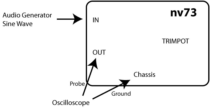
[*]Plug the Probe of your oscilloscope to the Hot and Cold (2 & 3) of the "OUTPUT" of your API lunchbox
[*]Plug the ground of the probe of the oscilloscope to the NV73 chassis
[*]Connect an audio generator that produces a 1Khz sine wave at 20dB or more to the "INPUT" of your API lunchbox
[*]Adjust your oscilloscope so that the sine wave reading is stationary
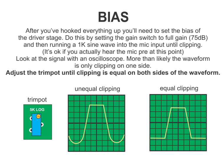
[*]Turn the trimpot until you get the clipping of the top and bottom of the sine wave on your oscilloscope as shown in the pic below
[/list]
Is this right?
Also in step 3, can you plug the probe directly to the output transformer instead of the API XLR output? If so, which part?
[list type=decimal]
[*]Adjust the trimpot till you get 22 volts using your multimeter connected to the 2N3055 and NV73 chassis
[*]Unplug the multimeter from the NV73 once you have done that
[*]Plug the Probe of your oscilloscope to the Hot and Cold (2 & 3) of the "OUTPUT" of your API lunchbox
[*]Plug the ground of the probe of the oscilloscope to the NV73 chassis
[*]Connect an audio generator that produces a 1Khz sine wave at 20dB or more to the "INPUT" of your API lunchbox
[*]Adjust your oscilloscope so that the sine wave reading is stationary
[*]Turn the trimpot until you get the clipping of the top and bottom of the sine wave on your oscilloscope as shown in the pic below
[/list]
Is this right?
Also in step 3, can you plug the probe directly to the output transformer instead of the API XLR output? If so, which part?
Onlymee,
Are you talking about adjusting the Bias as in Madrianse ez1290 builds. So adjusting the 22volts is actually adjusting the Bias??
I found this stuff from the EZ1290
So if I incorporate the EZ1290 instructions into your calibration,
Are you talking about adjusting the Bias as in Madrianse ez1290 builds. So adjusting the 22volts is actually adjusting the Bias??
I found this stuff from the EZ1290
So if I incorporate the EZ1290 instructions into your calibration,
- I would turn my Gain and Trim pot on full (65db) on my NV73 front panel
- Feed my sine wave into the lunchbox input
- Connect my osccilloscope to the output(Hot) and chassis
- Adjust my oscilloscope for a steady sine wave with one sided clip reading
- Adjust the trimpot till the clipping is at the top and the bottom of the sine wave just like in the EZ1290 pics
- That's it, the NV73 is now fully calibrated??
Yes that's all correct..
Step 3 you can take the signal reading from 2N3055 case if it's easier. Or pin 1 transformer. With your other probe referencing ground.. chassis or a ground pin.
Just whack a signal in.. turn up gain until the mic pre's output is just clipping. Then adjust.
(not important what gain level the pre is at.. it's just adjusting the output stage so you can also tweak the level of signal with the output trim if it's easier also .. as that is just attenuating the signal before the output stage - all as shown in schematic)
Hi guys,
i have succesfully built 2 NV73,
amazing project onlymeee , thank you !!
i have a problem on the third one,
i can't change the voltage on the 2N3055 with the trimpot
and i only have a few gain from the preamp,
i've checked all components, changed transformers etc..
but couldn't find the problem,
everything else seems working, gain switch,output pot,
phase and impedance switches,
can the problem come from a faulty 2N3055 ,
is there any lead i can follow to troubleshoot this unit ,
any help would be greatly appreciated,
regards,
Francois
I'd check the output transformer green molexs are definitely screwed in. Also that the transistors are in securely.
Make sure you reset the trimpot anticlockwise though before turn on if you think you've fixed the issue.
Is the 47R on the back of the PCB correct? Do you get a short between the casing of the 2N3055 and pin 1 output transformer ?
I'd also check voltages between the working ones and non working one.
thanks for your answer onlymee,
everything was ok except the 2N3055,
and i bought them on ebay from a electronic broker,
so i wasn't sure they were new .
i changed it and now everything is working fine !
thank you very much for this project !!
everything was ok except the 2N3055,
and i bought them on ebay from a electronic broker,
so i wasn't sure they were new .
i changed it and now everything is working fine !
thank you very much for this project !!
nielsk
Well-known member
Can someone please clarify, the pot wiring is not clearly shown anywhere that I can find. There is a point "P" over by the input tranny, and another point "P" by the 3055. This one has a point "L" (wiper?) next to it, but no point labeled GND (for the other side of the pot). The other P has a 0v right next to it....
nielsk said:Can someone please clarify, the pot wiring is not clearly shown anywhere that I can find. There is a point "P" over by the input tranny, and another point "P" by the 3055. This one has a point "L" (wiper?) next to it, but no point labeled GND (for the other side of the pot). The other P has a 0v right next to it....
If you look at the 2 links at the bottom of this page, it should show the wiring
http://www.thedonclassics.com/nv73manual.html
nielsk
Well-known member
That's perfect! I was operating under the impression those links were silk overlays...
Thanks")
Thanks
Hey all
I'm currently testing my NV73 and everything (still at 'testing before starting it up') seems to be as it should, except for the goldfingers.
PIN 14 should have a high resistance to PIN 13 and 12, but in my case I don't have a high resistance.
PIN 14 to PIN 13 has 430 kOhms-ish
PIN 14 to PIN 12 starts at around 35 kOhms and keeps dropping when connected to the multimeter.
Does anybody have an idea of what the problem might be ?
I put the NV73 in my API lunchbox and powered it on, adjusted the trim pot until I had 22V between the chassis of the 3055 and the ground.
Rigged a mic on it and it worked wonderfully. It had absolutely no noise or hum and the mic sounded very clean (by that I mean no radio signal or clipping or noise or anything, just as it should)
Still a bit confused about those goldfingers though..
Rigged a mic on it and it worked wonderfully. It had absolutely no noise or hum and the mic sounded very clean (by that I mean no radio signal or clipping or noise or anything, just as it should)
Still a bit confused about those goldfingers though..
Have a look at my journey thread and see if that helps clears things up?Mr.Franky said:Still a bit confused about those goldfingers though..
http://www.groupdiy.com/index.php?topic=41920.40
Hey canidoit
Yeah I had read your thread before, you had around 7 Momhs between those goldfingers if I remember correctly.
Therefore I found it so strange that my resistances are so much lower.. :s My NV73 sounds amazing though.
What are pins 12,13,14 for maybe ? On another forum I have read those are -15V, ground and +15V ?
So does anybody have an idea why my resistances are so low ?
Similar threads
- Replies
- 24
- Views
- 7K
- Replies
- 8
- Views
- 4K