Newbie builds U87 clone

GroupDIY Audio Forum

Help Support GroupDIY Audio Forum:

This site may earn a commission from merchant affiliate links, including eBay, Amazon, and others.
Biasrocks said:
There is no documentation error. The error is that everyone is turning there transformers around and totally screwing up the impedances.

The data sheet clearly shows that the primary leads were meant to be yellow, and the secondary leads black.  This was clearly not the case for at least some transformers.

Either the docs are wrong, or the transformers themselves were manufactured incorrectly.
 
If you read my post, I also said the output level will absolutely NOT match the 10db hotter output of the "A" version which is being compared to when they talk about missing level.

Matador said:
Either the docs are wrong, or the transformers themselves were manufactured incorrectly.

Regardless, the 200 ohm side (22R DCR) of the transformer needs to be on the output of the microphone, as per the Neumann schematic.

It's always a good idea to confirm the specs of a component.

Also, are you bypassing the output pad R20 & R21 in this build?

Regards,
Mark
 
Hey Mark,

I think we have a slight confusion here.

(At least) Some of the AMI T13 transformers have the colors for primary and secondary reversed,  AMIs data sheet shows yellow for primary (coupling cap) and black for output (XLR). My T13 had 22 Ohms an the yellow pair and 437 Ohms on the black pair. Connected according to the AMI sheet my microphone kind of worked but had a very low output, reversing the x-former (22 Ohms to output) resulted in a usable output level. People reporting having low output seems to have this issue NOT because they compare their builds with a U87A(i).

But you're right, always check the components....

Best,

Anders
 
Sredna said:
Connected according to the AMI sheet my microphone kind of worked but had a very low output, reversing the x-former (22 Ohms to output) resulted in a usable output level. People reporting having low output seems to have this issue NOT because they compare their builds with a U87A(i).

Hi Anders

The 200 ohm (22r) side of the transformer should be on the output side as per the Neumann schematic. You may have another issue if your experiencing a unusually low output level. Also make sure that the R20/21 output pad is not enabled.

Regards,
Mark
 
Hi Mark,

the x-former is now connected with the 200Ohm (22r) side as output and works very well indeed!

The issue was that the xformer first was connected according to the AMI data sheet wich obviously
doesn't correspond with at least some of the T13s out there.

The R20/R21 pad is not implemented in Poctops U87 version so this shouldn't be the reason of the low output problem.

Best,

Anders
 
Hi Anders,

yes, I have made the same experience here,the mic is now within the neumann specs concerning overall gain.It was off by far before the swap.

Best,

Udo.
 
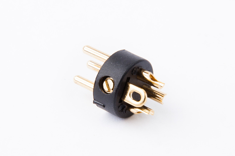
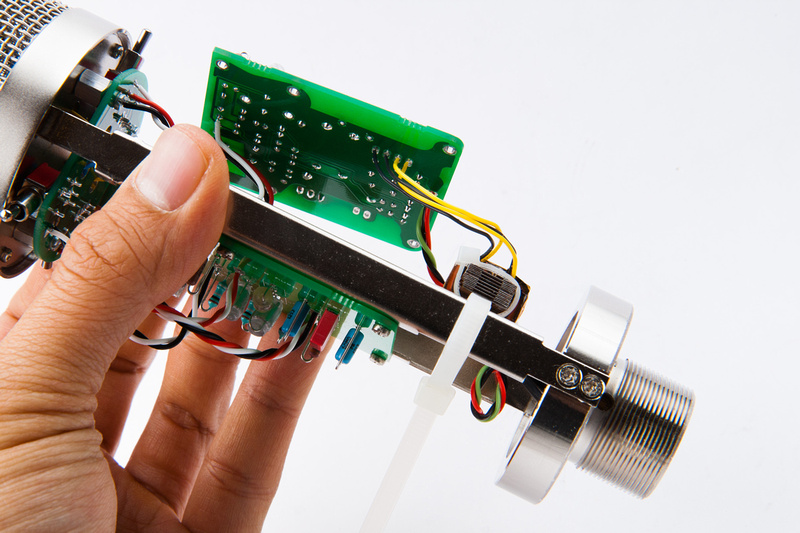
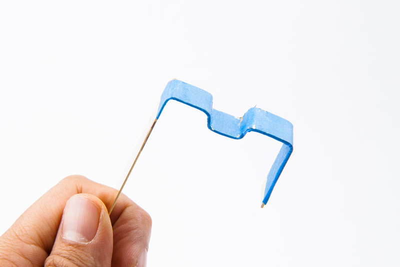
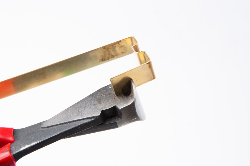
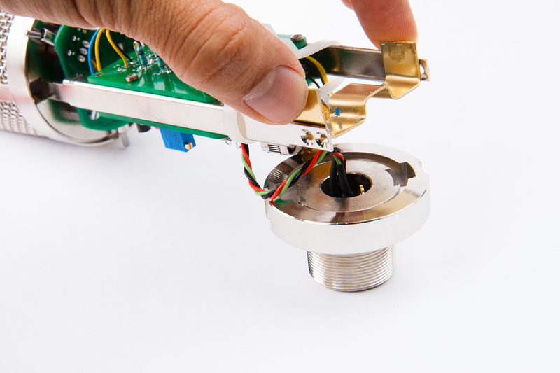
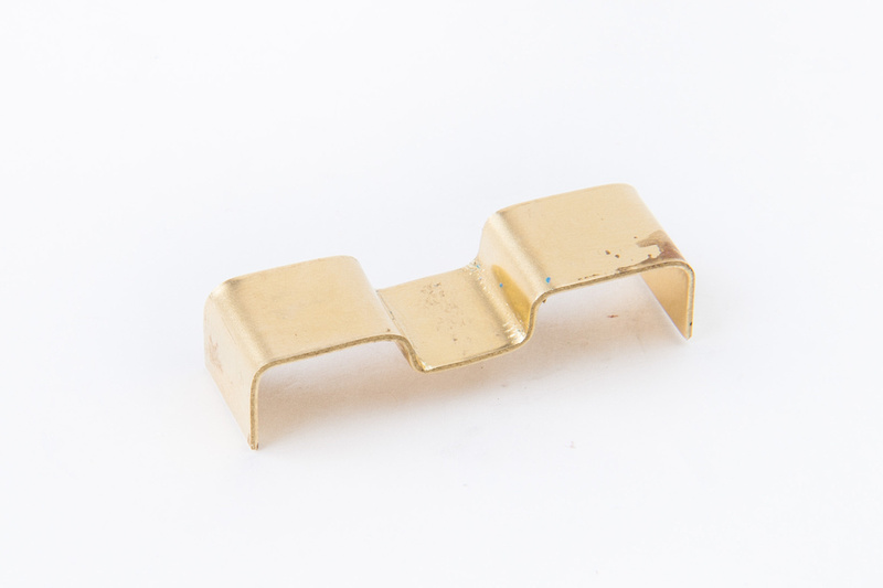
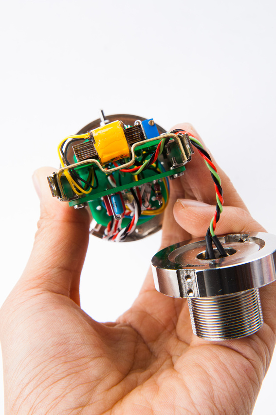
Next, up is the 3 pin XLR insert for the microphone.  These bodies are supplied with 3 pin and 7 pin xlr inserts.

p1299771184-4.jpg


p1299771222-4.jpg


The insert secures to the microphone body via a set screw that presses tightly outward to the body when twisted in the reverse direction.

p1299771296-5.jpg


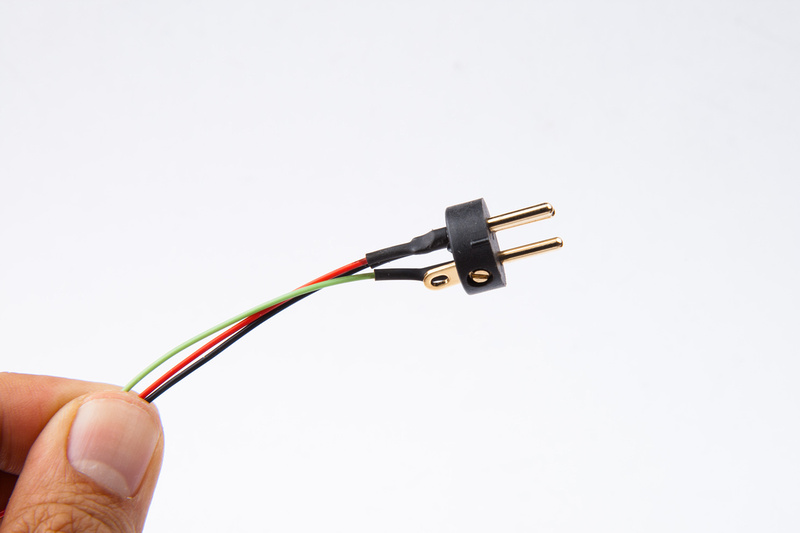
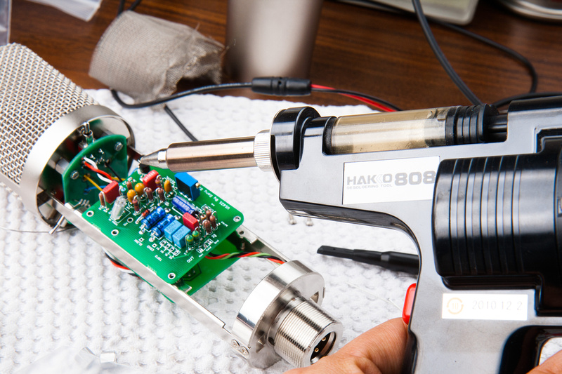
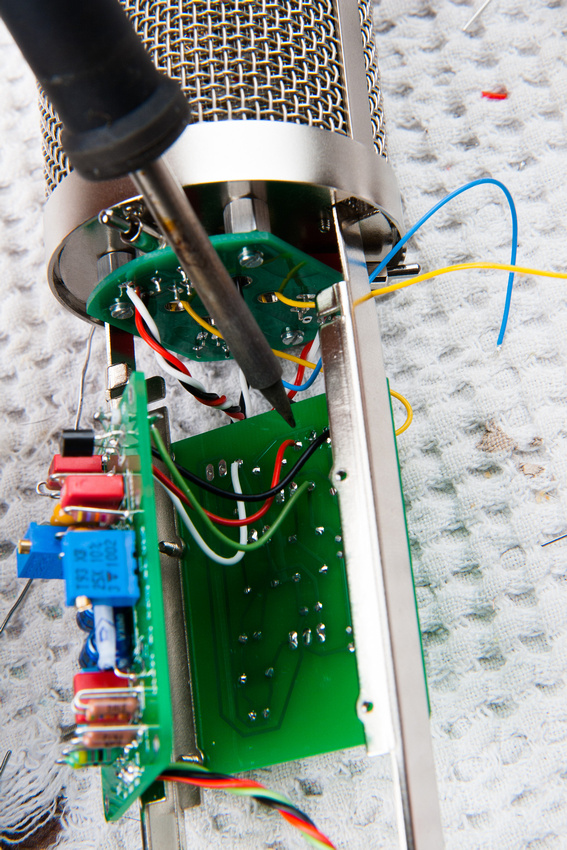
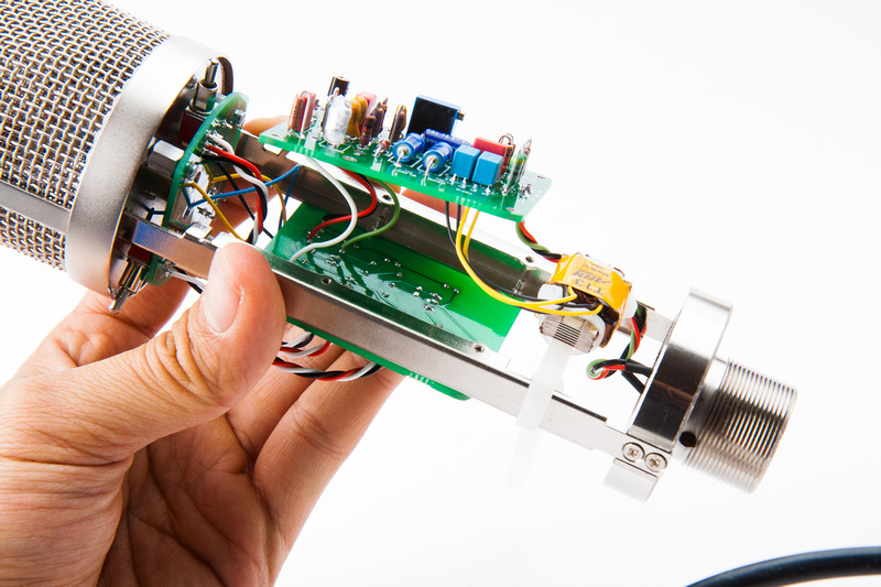
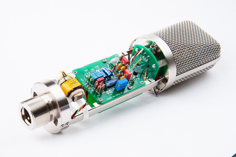
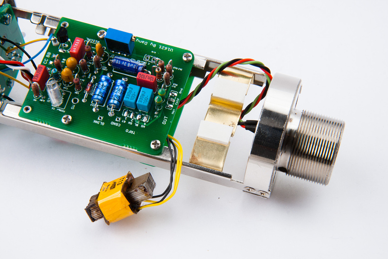
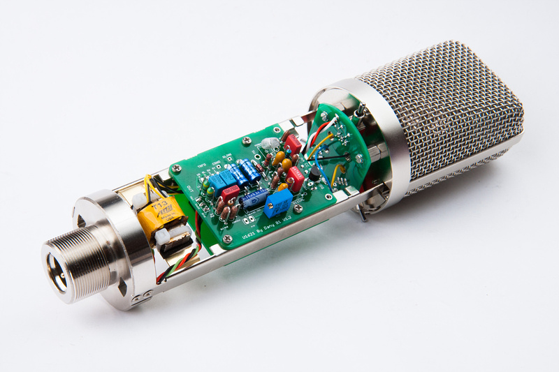
The build could be wired for a cleaner look with a shorter minimum length run of wire, but knowing me, I will have to get back into the PCB to make an adjustment or a correction at some point, so I leave enough slack in the line for future repairs, but not so much that it's overly ugly. . . just borderline-moderate ugly.

p1299771478-4.jpg


HAa ha!. .  . right on cue, the Hakko 808 comes out and I'm swapping components on the pcb.  What ended up happening is I made a mistake because I was measuring from the gate instead of the drain with my scope as I tried to bias the FET.  Very important to measure from the drain.

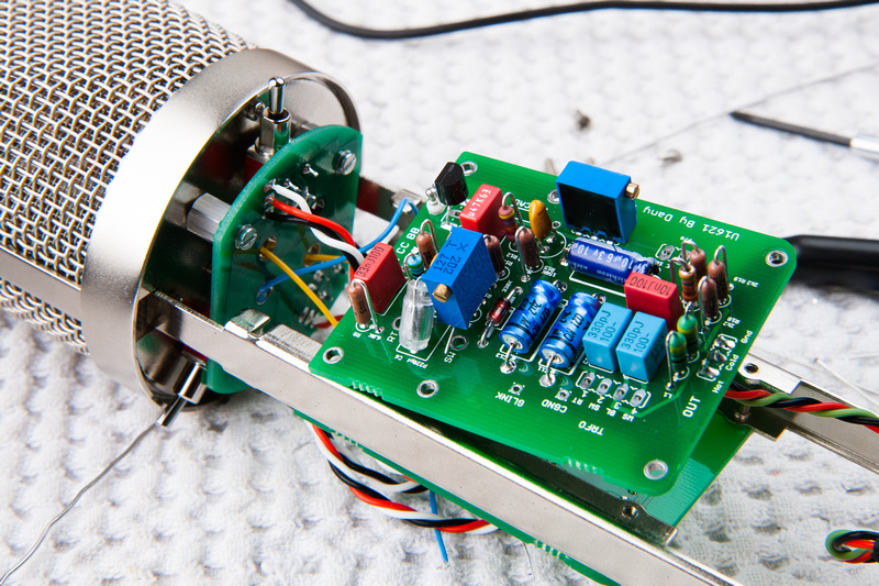
My voltages were good at the zener (23.6v) so reading through the thread, I replaced R14 (10K) with a pot.  Note, all of this was not necessary because I was silly and measuring from the wrong spot.

p1299771658-4.jpg


But, the extra slack in the xlr cable made repairs and changes much easier.

p1299771870-4.jpg


R14 replaced with a pot set to 10K

p1299772522-4.jpg


I adjusted R14 for a 3V drop across R14 according to the thread.

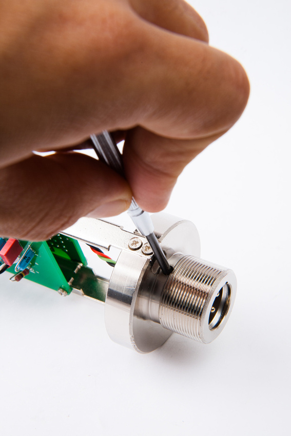
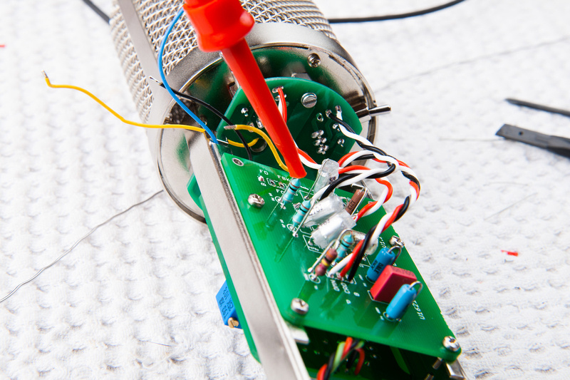
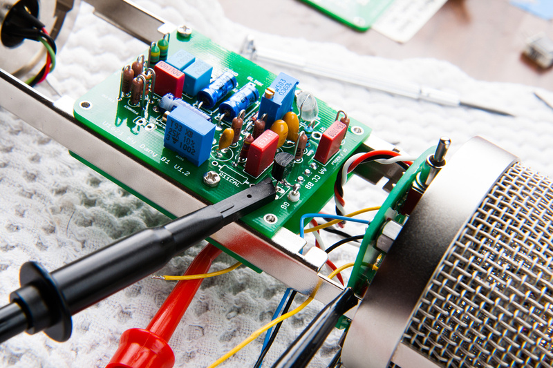
That was when I realized I should go look at the spec sheet for the FET and figure out if I was measuring from the drain, which I wasn't. . . and felt kindof silly.  Anyways, here is the correct spot to inject signal (without the capsule connected).  The is at R6 which is installed backwards from the silk screening per the build instructions.

p1304770614-4.jpg


And the correct spot to connect the scope.

p1299784478-4.jpg


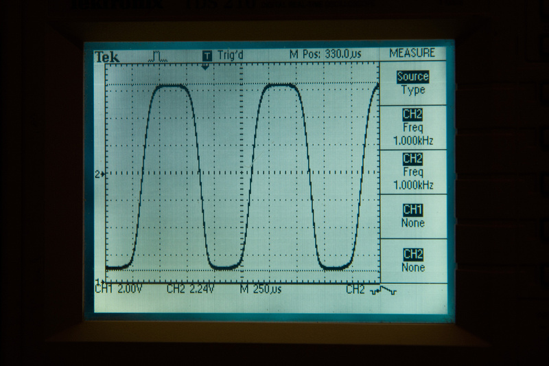
And, measuring from the drain, I was able to adjust the bias pot for symmetrical clipping.

p1299773226-4.jpg


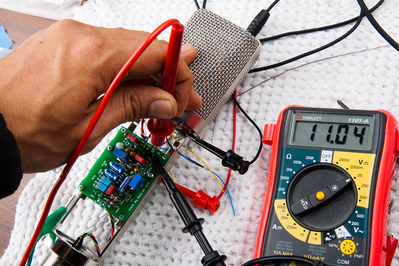
And for this FET in this mic, the drain voltage was 11.04V in this configuration.

p1299785148-4.jpg


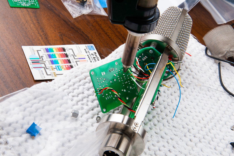
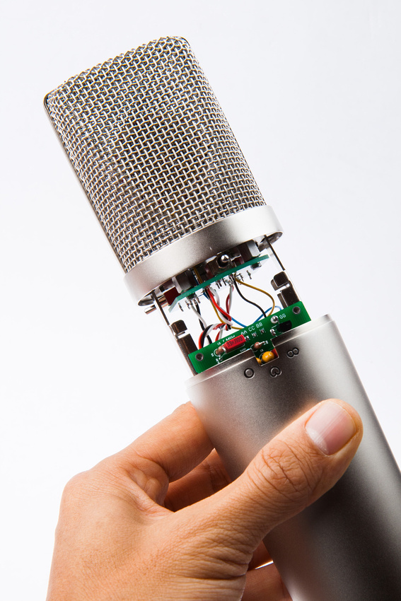
Next, I solder in my capsule connections.  When installing the capsule, I was sure to remember where the front and rear connections are.

p1299785940-5.jpg


And after some thought, I removed the pot at R14 because the build ended up being pretty solid.  I measured its final value at 18K to get a 3V drop across R14.  The stock value 10K yielded less of a drop, but I figured why mess with the circuit if it's working as originally spec'd.  I had to disconnect the capsule, insert signal again, and re-bias the FET with the original R14 back in, but since I was monkeying around inside the mic already, it wasn't too bad.

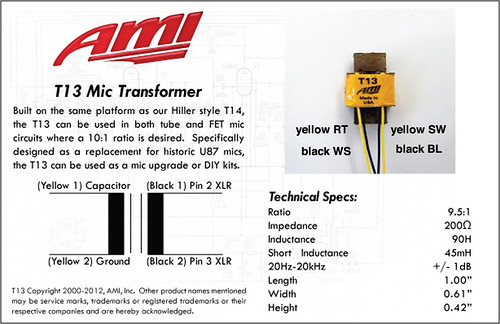
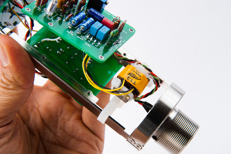
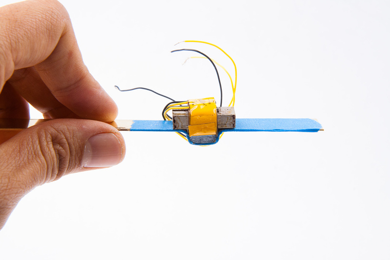
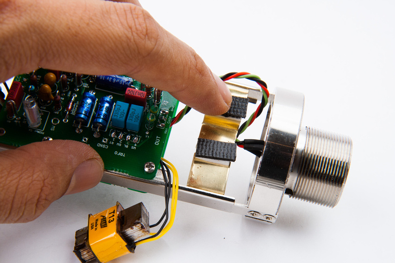
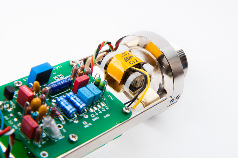
Next, I used some zip ties to attach the T13 transformer.  I could not make heads or tails of the silkscreen letter designations, so digging through the official build thread, I came across this image that Wave posted.

7174554600_240a084539.jpg


Because a large number of T13's were shipped with wire markings reversed from the spec sheet, I checked my transformer and it read about 21R on the yellow side and about 436R on the black side, so mine was reversed.  The higher resistance side (yellow in my case) should go towards the capsule side and the lower resistance side (black in my case) should go to the output xlr.

I didn't want to mess up my polarities so I tried following the diagram and reversing the colors since I don't have the foggiest idea what the silk-screened letter indications on the transformer pads mean.

so, with the transformer in the same orientation as the picture:

Left side black --> RT
Left side yellow --> WS
Right side black --> SW
Right side yellow --> BL

p1299786280-4.jpg


p1299786482-4.jpg


p1299786676-4.jpg


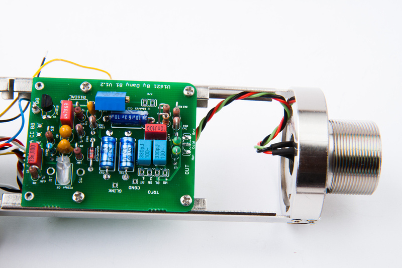
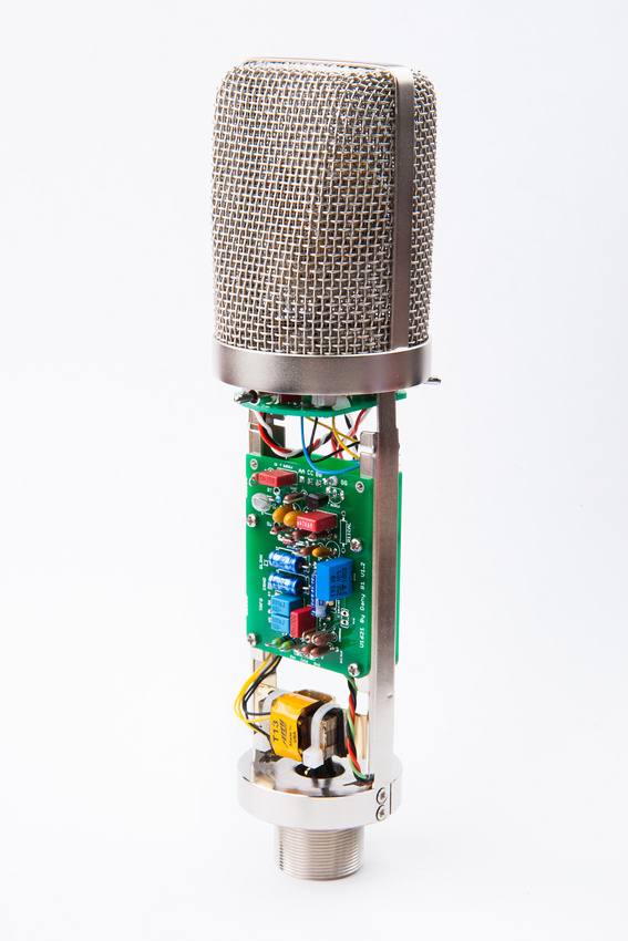
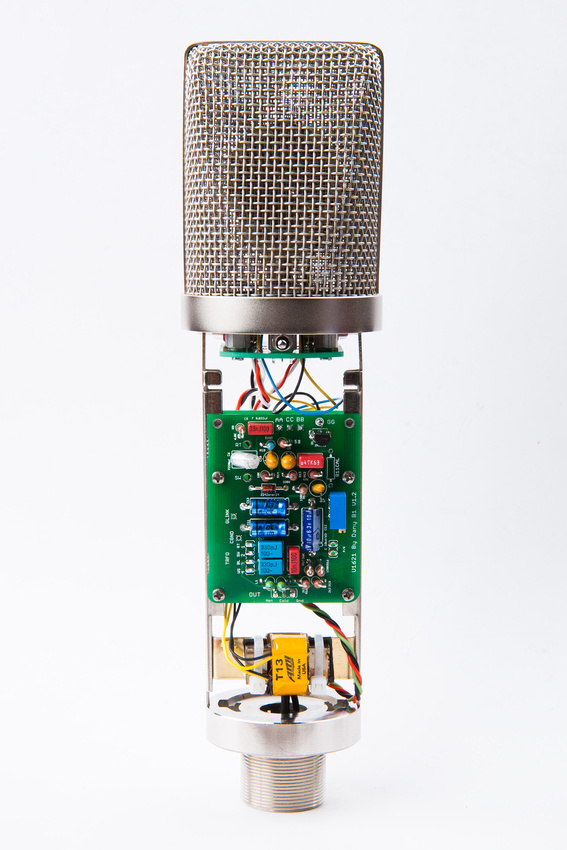
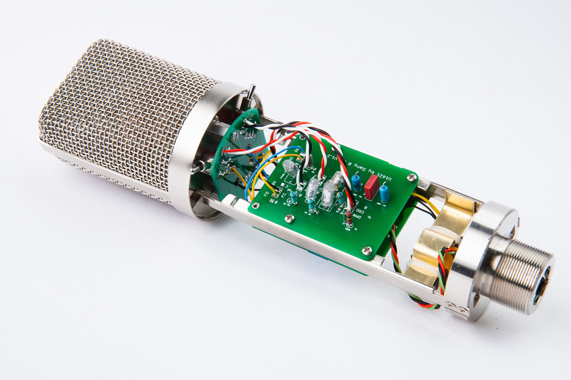
Once the transformer was installed, I proceeded to take beauty shots of the microphone interior because I thought I was done.

p1299787456-4.jpg


. .. and after my nice photo session of my "final" build, I discovered that the tube would not fit over the ziptie that held the transformer in place. . . DOH!  And I was so proud of my 3 zip tie solution.

p1301073780-5.jpg


After getting over my distraught, I headed to the local hardware store and found some small pieces of brass bar stock.  I bought a thick one that ended up being too tough to hand bend with pliers and a thinner one that proved to be a bit more manageable.

p1304900148-4.jpg


A bit of creative bending with needle nose pliers, and I create a little recess to keep the transformer centered.  Blue painter's tape somewhat protects the brass surface from tool marks. . . kindof.

p1304900376-4.jpg


And, we make our outside bends.

p1304900622-4.jpg


I use my fret cutters to shear through the brass stock, and it works pretty well and I have a fair amount of control and precision with my cut placement.

p1304900818-4.jpg


I leave the ends long, remove the base of the microhpone frame and determine my final cut points to make an exact fit.

p1304900996-4.jpg


Ends are cut to length.

p1304901264-4.jpg


A test fitting reveals that my tension fit is quite exact and sturdy.  I will not have to drill screw holes into the frame rails to support this.

p1304901352-5.jpg


Next, I make a few notches in the bracket to retain the zip ties that I will use to mount the transformer.

p1304901778-4.jpg


I position the bracket in its final location and use two small pieces of self-adhesive foam.

p1304901952-4.jpg


The double sided adhesive on the foam probably would have been fine for mounting the transformer, but I did not want to "stick" the transformer to the bracket just in case I mucked something else up inside the microphone and I would need to go back into it for repairs, so I found some very think foam and stuck those on top of the adhesive strips.

p1304902334-4.jpg


Two zip ties secure the transformer hopefully for the final time.

p1304903272-4.jpg


Alright!  Humans win.  Time to take some more beauty shots of the completed microphone internals.

p1304903646-5.jpg


p1304904136-5.jpg


p1304904588-5.jpg


p1304905022-4.jpg


p1304905488-4.jpg


Next, the cover goes on. . . and "Check, check, 1-2, 1-2, 1, 2, 3?"

p1304905892-5.jpg


Chunger,
Looks like the transformer is hooked up correctly to me. Im diggin your mount for the T13 too. Great work!

Dave
 
The mic's headed off to the studio to get broken in. . . one last detail I need to sort out is to raise the capsule a little bit to be proportionally a little closer to the Neumann U87 position in the headbasket.  A simple $.65 part will do the trick on this capsule mount and will be super-simple to install.  This is an M3 thread male to female threaded standoff that is 6mm height. . . or any height you feel like.

http://ca.mouser.com/ProductDetail/Harwin/R30-3000602/?qs=sGAEpiMZZMtrde5aJd3qw4L16p8RLiBx2s3%2flAVj2iM%3d

 
OK. . . early reports from the studio confirm that this mic is indeed working properly in it's current configuration and output level is very close to the 3 vintage U87's we currently have in studio to test against.

The tone and response of the mic is certainly right in there with the vintage brethren. . . well, let's not go so far as to call them brethren.  This is more a bastard child  ;D

Of particular interest is a vintage circa 1971 Neumann U87 that is also configured with a Peluso capsule (original worn capsule preserved and stored for originality) because the differences tone-wise would be contributed to circuit and body.  This clone is slightly brighter and snappy or forward, but well within the same vibe.  The caps may need to settle in a little bit and I believe the more open mesh of the clone body may contribute to the difference in treble response.  Also, the FET in the vintage mic may be the Texas Instruments unit that is long out of production, so that may have influence on tone..  . well, along with different caps, different transformer, and many many places that shifts can occur even on the same audio circuit.

At any rate, so far, the performance is impressive, and my friend who operates the studio indicates that upon initial impression, he would not have issue with substituting this microphone for the vintage unit for all practical purposes.  Money will certainly be saved here as this is one of the more affordable mic projects even if utilizing "best of breed" components throughout.  It is not a matter of one being particularly superior to the other.  They are a lot the same and a little different.  The deviation does not seem to be greater than the differences we hear between the 3 vintage mics. . .or course, age and condition also vary greatly between the 3 vintage samples we have on hand.
 
Comparing a Peluso U87 capsule with a Neumann capsule is apples to oranges. I haven't heard a Pelsuo clone capsule that comes close to the sound of a good example of a vintage Neumann capsule.

I have not heard one comparison where the U87 clone has nailed the sound of the original, it's a very distinct sound.

I'm trying very hard to maintain a level of objectivity in this electronics forum. Empirical evidence is always better.

I'd be interested in hearing a well maintained example of a vintage U87i with the a known good Neumann capsule against the clone. I happen to have one here in the studio and would be more than willing to do some comparisons.

Acoustic guitar, vocals and VO would be very telling.

High resolution sound samples would be appreciated.

Regards,
Mark
 
Biasrocks said:
Comparing a Peluso U87 capsule with a Neumann capsule is apples to oranges. I haven't heard a Pelsuo clone capsule that comes close to the sound of a good example of a vintage Neumann capsule.

I have not heard one comparison where the U87 clone has nailed the sound of the original, it's a very distinct sound.

I'm trying very hard to maintain a level of objectivity in this electronics forum. Empirical evidence is always better.

I'd be interested in hearing a well maintained example of a vintage U87i with the a known good Neumann capsule against the clone. I happen to have one here in the studio and would be more than willing to do some comparisons.

Acoustic guitar, vocals and VO would be very telling.

High resolution sound samples would be appreciated.

Regards,
Mark

poctop said:
Here is what my Clone sounds like the clip is very raw ( No pop filter to have an idea of the proximity effect ) but at same gain setting
D.
https://cdn.groupbuilder.com/groupdiy/u/39511/58d02819939a4.wav

Edit : when i say it is very very flat i am tlaking about the extra sweetness with the original capsule.
Got the year october 1979 
Dan,
 
poctop said:
Here is what my Clone sounds like the clip is very raw ( No pop filter to have an idea of the proximity effect ) but at same gain setting
D.
https://dl.dropbox.com/u/43869772/U1621/du87%20and%20original%20comp.wav

Edit : when i say it is very very flat i am tlaking about the extra sweetness with the original capsule.
Got the year october 1979 
Dan,

Interesting, I'm not hearing the characteristic low mid presence in any of those samples.

I'm not sure what an absence of a pop filter has to do with proximity. Using one
would help to maintain a consistent distance from sample to sample, but would
not add or subtract from the proximity effect.

Curious what the setup was for the test, pre-amp, converters, sample rate.

Regards,
Mark
 
Biasrocks said:
poctop said:
Here is what my Clone sounds like the clip is very raw ( No pop filter to have an idea of the proximity effect ) but at same gain setting
D.
https://cdn.groupbuilder.com/groupdiy/u/39511/58d02819939c2.wav

Edit : when i say it is very very flat i am tlaking about the extra sweetness with the original capsule.
Got the year october 1979 
Dan,

Interesting, I'm not hearing the characteristic low mid presence in any of those samples.

I'm not sure what an absence of a pop filter has to do with proximity. Using one
would help to maintain a consistent distance from sample to sample, but would
not add or subtract from the proximity effect.

Curious what the setup was for the test, pre-amp, converters, sample rate.

Regards,


Mark


I was expecting nothing more than this from you that my original Neumann was not good enough,  :eek:,
you may as well say that Doug walker the guy who reskinned my original capsule is doing a crappy job.
 
poctop said:
I was expecting nothing more than this from you that my original Neumann was not good enough,  :eek:,
you may as well say that Doug walker the guy who reskinned my original capsule is doing a crappy job.

I have had a Doug Walker reskin here, was not impressed.

Thiersch's reskins are much truer to the original sound.

I hoped Doug's reskin would be superior as I like supporting fellow countryman, was not the case.

At least we know your capsule is not an original, aside from the backplate which explains why I'm not hearing the
characteristic U87 sound in those samples.

I see you've ducked the question about how the test was performed.

Regards,
Mark
 
Biasrocks said:
poctop said:
I was expecting nothing more than this from you that my original Neumann was not good enough,  :eek:,
you may as well say that Doug walker the guy who reskinned my original capsule is doing a crappy job.

I have had a Doug Walker reskin here, was not impressed.

Thiersch's reskins are much truer to the original sound.

I hoped Doug's reskin would be superior as I like supporting fellow countryman, was not the case.

At least we know your capsule is not an original, aside from the backplate which explains why I'm not hearing the
characteristic U87 sound in those samples.

I see you've ducked the question about how the test was performed.

Regards,
Mark


I have done the test with a wav 44.1KHZ 16bit rendered with Martin 1290 pre in RME FF800  ,  but once again i am not surprised that you
are trying to Discredit  Doug Walker Work as well.  :eek:
also you should let know Bill Carter At Sennheiser that has been recommendend him for the last 25 Years that he is an idiot :eek:
I think i am really done arguing with you anywhay.


poctop said:
I have done the test with a wav 44.1KHZ 16bit rendered with Martin 1290 pre in RME FF800 

Ah, okay. Not really what I would call a definitive test.

Have you heard the difference between audio recorded at 24/88.2kHz audio recorded to 16/44.1kHz?

It's not subtle.

I've got a dozen high end pre's here feeding Apogee 16X converters, I think I have a good frame of reference.

How about when the microphone is compressed on the way in, as would happen in many circumstances. That certainly tends to highlight more of the differences.

you are trying to Discredit  Doug Walker Work as well.  :eek:
also you should let know Bill Carter At Sennheiser that has been recommendend him for the last 25 Years that he is an idiot :eek:

"Idiot, discredit" are your words not mine.

I simply pointed out that I didn't prefer Doug's reskin over a Thiersh. I thought that Dougs was lacking when compared to the Thiersh.

That's called an opinion.

Have you heard one capsule next to the other?

You seemed determined to make this personal and try to single me out as an extremist, someone who will always find an issue for sake of argument. I assure you that simply is not the case. I don't know how many times I've read, heard and ultimately been disappointed by a piece of kit thats 'just like' a well known studio standard. There's plenty of other places that embrace that kind of propaganda.

Sure, the mics sound similar given your compromised testing criteria.

As I offered before, I'm willing to do a test here. I doubt you'll take me up on it.

Regards,
Mark
 
Biasrocks.
I really encourage you to build one and try it out, i was not impressed at all by samples we hear over the web.
However i ended deeply impressed on how good it sounds, im not saying it sounds the same it just cant be.
we are not using same caps and transformers are not the same, but sound is the same ballpark.

comparing originals to diy clones is like comparing apples and oranges, despite the fact that they are the same circuit.
 
Back
Top