Noob: Replacing 3 caps in a chinese large diaphragm.

GroupDIY Audio Forum

Help Support GroupDIY Audio Forum:

This site may earn a commission from merchant affiliate links, including eBay, Amazon, and others.

mrelwood

Member
Joined
Mar 31, 2005
Messages
19
Location
Finland
Hello.

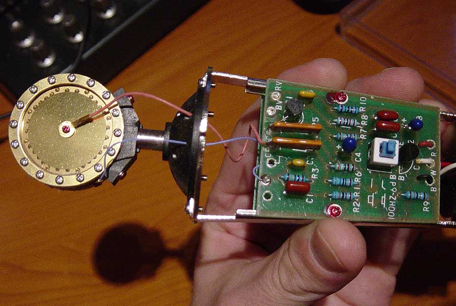
I found a zillion posts regarding this process, but I can not locate the two .22nF caps in my mic that usually are replaced as a first mod. My mic is a chinese made TSM MT87, mostly marketed in Scandinavia. Diaphragm measures 32mm, and there are 16 screws (?!) both sides holding the frame. The mic looks very close to a more popular chinese I saw a picture of somewhere, but don't remember which one.

TSM_MT87_001_small.jpg


I can locate the "Gate" cap (C2), 1000pF ceramic, and I'm going to replace it with a polystyren one, if available. I cannot locate the other two. The schematic is a fastly drawn one, haven't had time to draw it clean on a computer yet. I hope you hawk-eyed pros can make some out of it. :)

The gate cap is marked with circle in this schematic:
TSM_MT87_Schematic_draw.jpg


The ones I suppose are the ones to be replaced are circled here. They read "330I".
TSM_MT87_Schematic2_draw.jpg


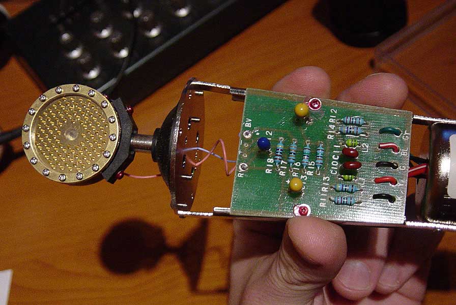
The ones marked at the lower schematic would be the red/brown ones at the back of the mic:
TSM_MT87_002_small.jpg


Also, I was wondering if I should try removing the inner layer of metal wire net that is protecting the diaphragm, to get a bit more open sounding mic. The outer and inner wire nets are the same thickness, and between them there is a tighter, thinner one. Would it do any good to remove the inner thicker one?


Thank You very much if there is any help you can give me!

-Aki.
 
They might be the two sharp-edged yellow caps off to the right side - differing values (47 instead of 33) can happen with these mass production mics. But look like film caps anyway...
 
No, your mic is not like the ones that use the two .22uf caps. Yours is the same as the MXL 2001. It uses a transformer coupled output. You can replace C2 with a 1000pF polystyrene, C4 and C8 with high quality electrolytics, and C6 with a high quality film or metal film. That may improve it some, but the biggest problem you have is the transformer. It?s laminates are made from ultra cheap Chinese scrap metal and it sounds bad. You can either re-laminate it (info is in the META I think) or replace it with a Lundahl or some other high quality transformer, or do like I did and replace the entire circuit with a Schoeps type circuit (pc boards are available from Scott Dorsey, [email protected]).
 
Aki

You are not looking hard enough!
The 1000 pf cap i.e. .001uF cap labeled 102 on the cap body.
which is 10 with 2 zeros which equals 1000 pf.
It is under the board! the cap is attached to the two Teflon standoffs.
Look for the 2 big flat 1 Gig ohm resistors near top edge of board.
They also tie to the teflon standoffs.
The small monolythic yellow ceramic cap marked 102 is the one
to replace.

Be very carefull and do not touch that are with your fingers.
Skin oils will lower the resistan of the PC board remember
the 1,000,000,000 ohm brown resistors! It does not take much.
Clean you board with a lot of alcohol.

Use these caps;
http://www.mouser.com/catalog/621/542.pdf
look for 85°C AXIAL 5% POLYSTYRENE CAPACITORS
 
[quote author="Flatpicker"]No, your mic is not like the ones that use the two .22uf caps. Yours is the same as the MXL 2001. It uses a transformer coupled output. You can replace C2 with a 1000pF polystyrene, C4 and C8 with high quality electrolytics, and C6 with a high quality film or metal film.[/quote]

Thank You! Exactly what I meant! C4 is "226" +16, C8 is "475" +35, I suppose they have to be replaced with the original values even if they are different?
How do I ask for a "high quality electrolytics"? Do they know what to sell me even at a local electronics store?
About the C6, did I understand correctly that polystyrene and polyprop are both "film" caps?

I know that the tranny is the weakest link. I am going to buy new condensers as soon as our local store gets me a bunch of MXL's for testing. Until that, I'll be perfectly happy with a small mod like this.


Thanks!

-Aki.
 
Wait - if it's like the SE2000, then it isn't the same as the 2001 (which doesn't have a switch -my bad!). In this case you only need to replace C2 with a 820pF-1000pF polySTYRENE and C8 with a 4uF-10uF Panasonic FC series or other low impedance electrolytic. And remember Adrian's advice about cleaning the board around the FET.
 
[quote author="BYacey"]The mic in the picture doesn't appear to have an pad or low end roll-off switch...[/quote]It appears to have a lo-cut switch (blue and white thing next to D2) just like the schematic.
 
asm: "...what are the teflon standoffs?" If you look at Aki's first picture you can just make out a little white ring around each of the three connections on the top edge of the board (two of which terminate the wires from the capsule). These are teflon standoff terminals and have very high insulation resistance if not contaminated.
 
That china microphone looks like the insides of the sam ash ld1.

Change the 1000pf between the capsule and gate.

The transformer seems to be the the real limit with that china microphone design. The stock tants are not bad they have good forming voltage so changeing them to Al electros sometimes might not be a sound you are after.

If you find a neumann u87 schematic you will see the china microphones use a filter network kind of like the u87.

The type of chinas microphone uses a emitter follower after the fet so a 2:1 transformer can be used instead of a harder to get right 7:1 or so for a single fet stage like a u87, km84 circuit. I don't know what the lams are in the stock transformers.

One of the best thing to do with that capsule is a Royer tube circuit IMO.
 
[quote author="Flatpicker"]Wait - if it's like the SE2000, then it isn't the same as the 2001 (which doesn't have a switch -my bad!). In this case you only need to replace C2 with a 820pF-1000pF polySTYRENE and C8 with a 4uF-10uF Panasonic FC series or other low impedance electrolytic. And remember Adrian's advice about cleaning the board around the FET.[/quote]

Flatpicker, You are being extremely helpful! I almost feel like I should pay for this good a service! ;-)

It took me a while to realize that the two resistors actually ARE 1G! I though I didn't understand what You were talking about... When I first opened the mic, there were severe solder spills under the resistors R7 and R8. There is definitely some serious cleaning to be done. I suppose regular electronic cleaner or contact cleaner CRC doesn't help?

SE2000 schematic looks identical. My pics might not be most educating, our better camera is with my parents on their holiday trip. And yes, the mic does have the low cut switch. Haven't used it though, someone taught me to be afraid that it will mess the frequency response in other areas also. Should try that to know, though.

How does different values for the C8 affect the mic? Or should I just try different values and test the results?


Thanks!

-Aki.
 
[quote author="mrelwood"]Flatpicker, You are being extremely helpful! I almost feel like I should pay for this good a service! ;-)[/quote]It's all a matter of give and take, my friend. These other folks have contributed a great deal of information as well. Gus used to help me a lot with questions like this. I'll let you help the next person that ask this question.

I suppose regular electronic cleaner or contact cleaner CRC doesn't help?
Alcohol should work.

How does different values for the C8 affect the mic? Or should I just try different values and test the results?
The larger the value, the lower the frequency it lets through. 4uF may be plenty, but 10uF sure won't hurt it. Gus is right about the tantalums, the sound will change when you switch to eletros. In my experence it usually gets brighter and that may be a bad thing with this mic. I'd just try replacing C2 for now.
 
Okay...

I am having a bout of dejavue ....

This is the inside of my 'prized' ADK-51 mic.... man, isn't it nice to know that the marketing hype is just that... hype.... I think I am going to start my own mic company, all I need is a few dollars, a chinese factory and a good catch phrase oh and it helps to and use words like 'That Esoteric Vintage German Sound'... I'll be stinking rich!

ADK_A51_Front.jpg


ADK_A51_Back.jpg


Maybe I'll try the recommened cap mods on this thing... what is the worst that can happen...

Cheers

Matt
 
Once upon a time, someone told me that the difference between the A51 and other similar mics was two resister values. It'd be kind of fun to know what they were. Can you compare yours to the SE2000 schematic (Bill posted a link on page one) and see if you can tell which ones are different and what value they are?
 
I have to apologize for the missing component values on the schematic. I drew this while in flight to Vancouver, and I wasn't able to visibly identify the value on some of the parts. Sometime in the near future I'll remove the parts and measure them to update the schematic. I notice that I missed the pad switch as well...
 
Back
Top