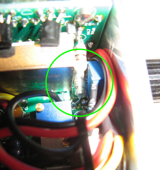
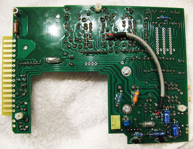
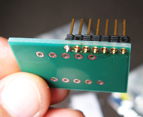
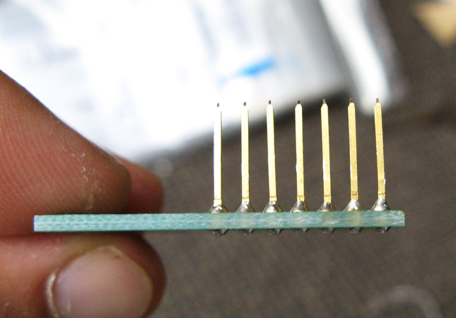
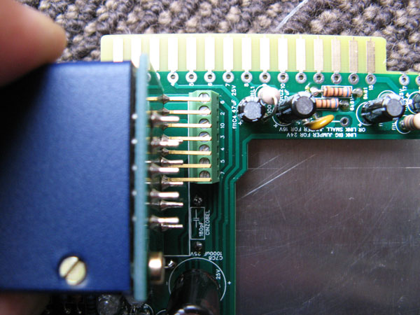
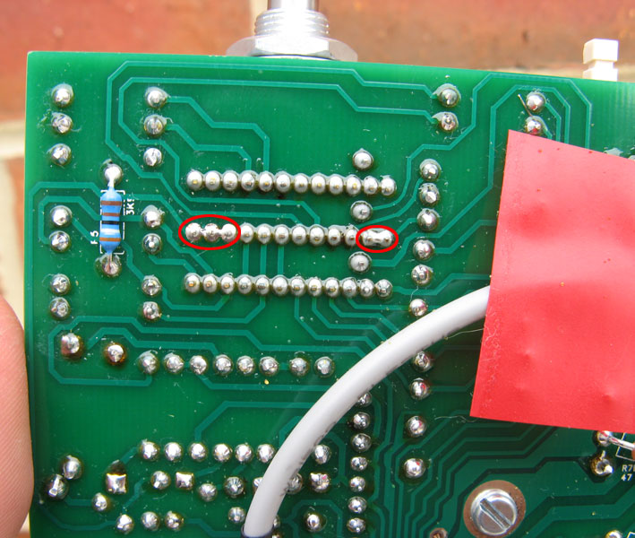
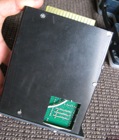
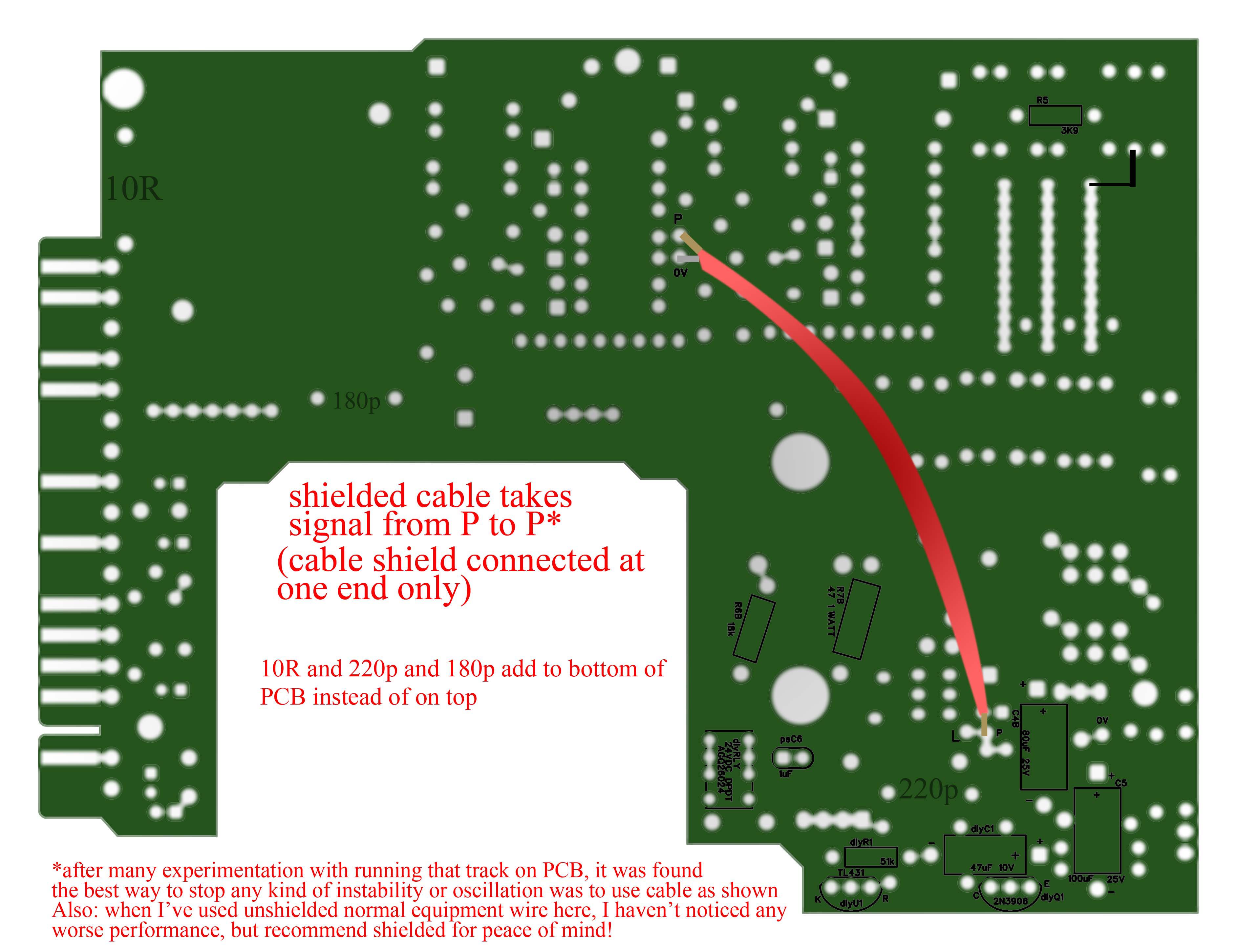
P wiring at the underside of board
As in one of onlymee's diagram pic, using single core shielded cable I connected the core of the cable to P to *P of the board and shield to 0 of the board and cut the other shield on the other end connected to nothing.
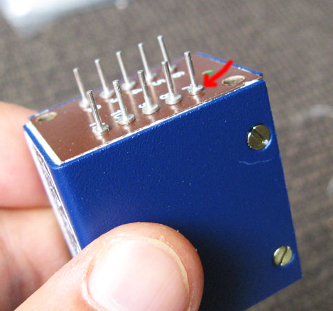
I used about 9.6cms in length of the single core shielded cable for this. I used a patch of electrical tape to keep the wire against the board to keep it tidy which is not in the picture below.
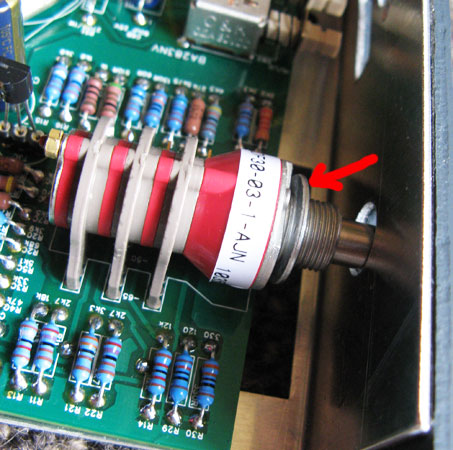
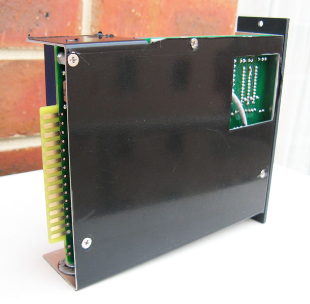
* the little white stand offs for all the PCBs is best to angle them parallel with the board to minimize protrusion and keep the length and width of the unit within requirements.
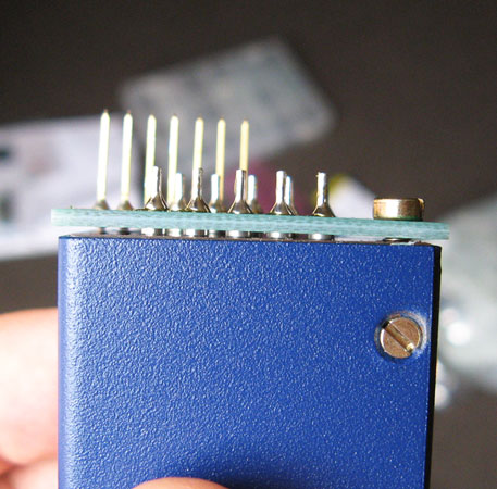
As in one of onlymee's diagram pic, using single core shielded cable I connected the core of the cable to P to *P of the board and shield to 0 of the board and cut the other shield on the other end connected to nothing.
I used about 9.6cms in length of the single core shielded cable for this. I used a patch of electrical tape to keep the wire against the board to keep it tidy which is not in the picture below.
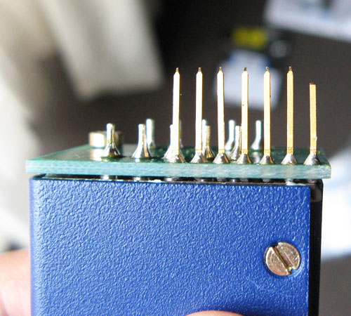
* the little white stand offs for all the PCBs is best to angle them parallel with the board to minimize protrusion and keep the length and width of the unit within requirements.


")