NV73 preamp - journey

GroupDIY Audio Forum

Help Support GroupDIY Audio Forum:

This site may earn a commission from merchant affiliate links, including eBay, Amazon, and others.
Calibration - from Don Classics website http://www.thedonclassics.com/nv73manual.html

TESTS BEFORE TURN ON:

TRIM POT MUST BE TURNED COMPLETELY ANTI-CLOCKWISE
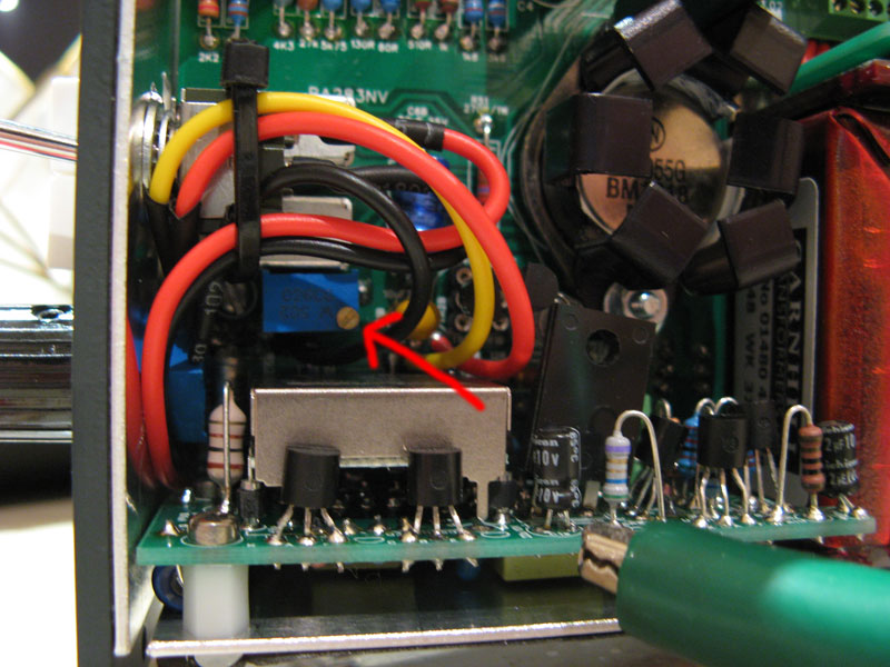
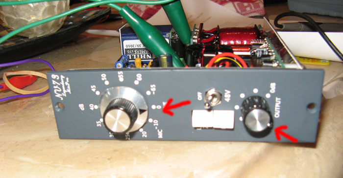
nvCalibrateA1.jpg

nvCalibrateA2.jpg


THE CASE OF THE 2N3055 MUST SHORT TO THE FIRST TERMINAL OF THE OUTPUT TRANSFORMER (PIN 1)
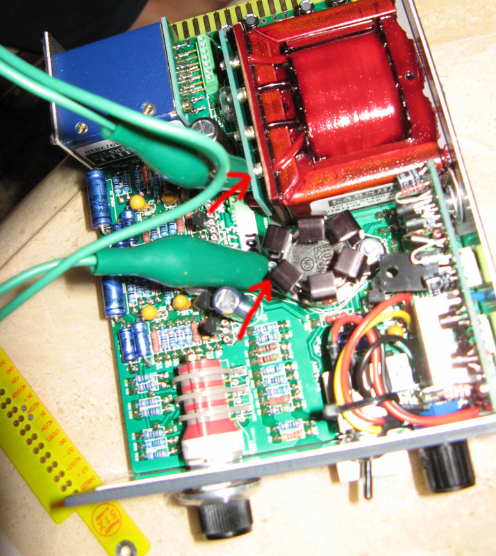
nvCalibrate1.jpg


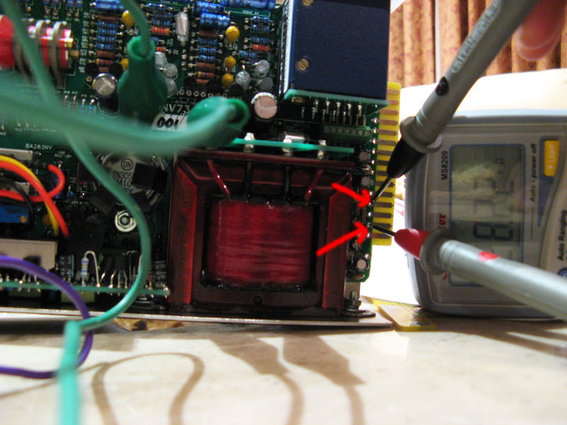
PIN 1 OF OUTPUT TRANSFORMER MUST NOT HAVE A RESISTANCE TO GROUND (SHOULD READ OFF THE SCALE OF YOUR MULTIMETER)
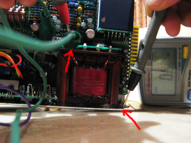
nvCalibrate2.jpg

My multimeter reading is "O.L."

SAME AS ABOVE FOR PIN 3 OF OUTPUT TRANSFORMER
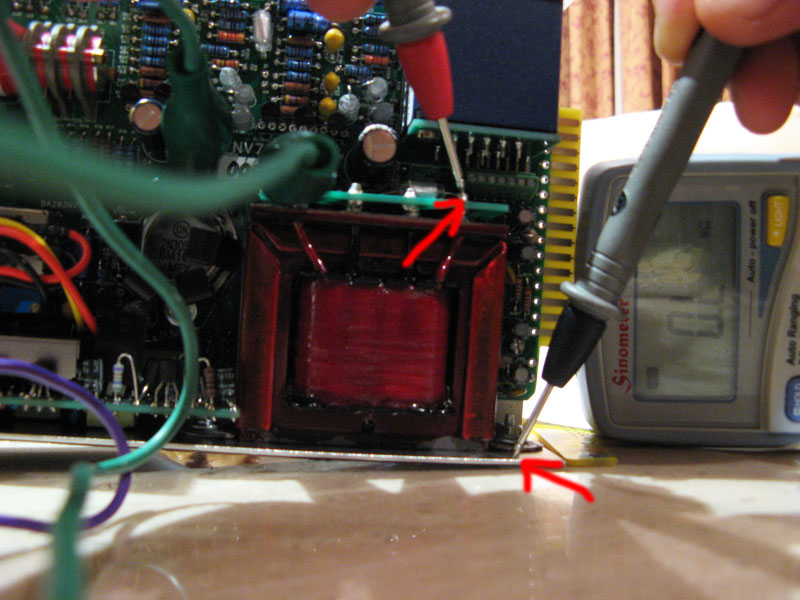
nvCalibrate3.jpg

My multimeter reading is "O.L."

ON THE GOLD FINGERS, PIN 14 MUST HAVE A HIGH RESISTANCE (NOT SHORT) TO PIN 12 OR PIN 13
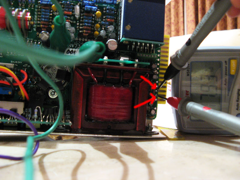
nvCalibrate4.jpg

nvCalibrate5.jpg

My multimeter reading is between "19-20MOhms"


TEST AFTER TURN ON

Make sure with one multimeter probe on the metal work and the other on the case of the 2N3055; test the voltage. MAKE SURE YOU GET A VOLTAGE OF NO LESS THAN 21V. IF YOU DO... TURN OFF IMMEDIATELY AND CHECK THAT YOU HAVE TURNED THE TRIM POT COMPLETELY COUNTERCLOCKWISE. (YOU SHOULD HEAR A CLICK EACH TIME YOU TURN WHEN YOU ARE AT COUNTER CLOCKWISE)

When fixed, you may turn the trimpot clockwise while measuring the voltage on the case of the 2N3055 still. When you reach 22V, it is set about right. An oscilloscope is needed for precise adjustment. (Adjust until both sides start to clip at the same time)

At this point, you can either test voltages at the legs of the BC184C transistors, or put some audio through it. When testing voltages on live circuits, you MUST be extremely careful not to short any pins together with the probe as the unit is turned on. If you are not confident doing this, you should plug some audio through it and only worry about testing further if your unit is not working correctly.
.............................................

I adjusted the trimpot till it read 22volts on my multimeter. When I connected an Oscilloscope and fed the NV a sine wave, and placed the two front panel knobs at maximum, I instantly got the clipped sine wave. It was a little blurry in some areas of the sine and occassionaly I would see a second clipped sine wave appear intermittently. That was the best result I was able to achieve with experimentation and so left it as it is. I measured my voltage when I placed both front panel knobs at maximum and I was getting 21.28 volts at probe at 2N3055 and ground at chassis.
 
Comments

Installing DC-DC board improvement
This is a rather tight build and I would have preferred if the approach in connecting the DC-DC board to the main board was better. You have to really use a pretty thin and long flat head screwdriver and at an angle to tighten the little molex. Getting the screwdriver at a nice angle is difficult since there are other components in the way. I think this could be prone to overtightening or wearing out the little molex screw heads especially if you are disassembling the unit for repairs.

I think this could be improved or a better approach to how to install it because you have to remove the heatsink each time you need to access the little molex. Maybe a connector could be used or it could be configured differently on how the DC-DC board is installed.

Just a thought...
 
That's mine :).

The "thing" :):


Lab Lunchbox:


This is a way to make some room for the small PCB:


I hope you find this useful in any way if you are doing this preamp.

cheers.
 
kato said:
Cool. I dig your "lab lunchbox." It looks like you built it out of aluminum L-channel? I'll have to try that.

Thanks mate, yeah it is aluminium L-channel. I did because I wanted to adjust and test the module before attaching it to the 511 lunchbox and it did the job.
cheers.
 
This seems to be the active thread for the NV73, if I should post elsewhere please let me know.  I have just finished 2 of these. 

BTW. Wonderful kit, nice metalwork, well thought out and a very nicely labled PCB. 

Post modified... previous diagnosis was wrong.
 
Hi Bruce,

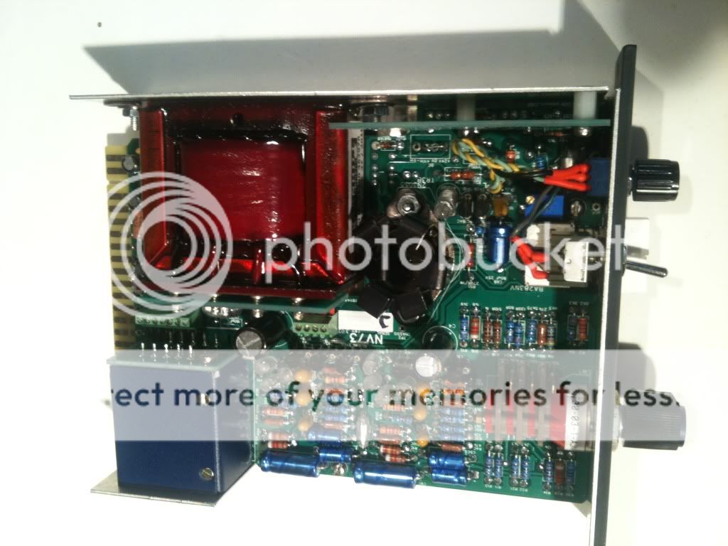
I did this preamp, I am not an expert but as far as I know if you have those "blue dots" components fitted is ok despite of you are not using the small PCB because the 4 pins for the Small PCB are not connected. But you should make a jumper there as picured in "red" to feed with the +24volts the preamp.

Also you have there another jumper marked in "red" as well (close to the blue dots) that you have to fit, if you are using +24 volts it should be the "big jumper" NOT the small one.

If you already did all above mentioned then your preamp should be working fine. Be sure you have GND on all PIN1 of the XLR in/out, I mean PSU GND, and also that GND should be shared with Audio GND and Chassis. Double check on the faulty Preamp if your jumpers are OK and try to swap them in your 511 rack as well.

Hope this helps. Good luck mate!
cheers.
 
I believe both jumpers are required.  If I leave off the small jumper (where the little PSU card goes, over to the left marked in red) then there is not 24V on the 2N3055 case.  The working one has both red jumpers (the jumper near the back is a fuse in my case).

The blue components are not needed, but marked as "no harm if fitted).  I fitted them because I thought I might downgrade to 16 V operation later.  But I think that  might have caused my problem.

I think something is wrong with my "slow start" circuit.

This is operating on my bench test unit, and I believe the two grounds are tied to chassis - checking now - but one unit would not work if the grounds were not tied, so I don't think that is it.  I tested both units in the same bench test unit (it is a breadboard 1 slot unit like Igor's Rackit.  But I want to get one of those Rackit ... I think they would make a nice little 2 slot unit).


I had a problem with the slow start circuit it would never come up.

I may be using the wrong schematic http://thedonclassics.com/NV73%20schematic_rev1-01.pdf but I cannot find the slow start circuit on it anywhere!


Actually I had two problems, both fixed now.  And both I am sorry to say solder bridges (sheepish grin)

The Input transformer card had a solderbridge on it.  Anyway, it was connecting pin 2 and 10 or 2 and 6, and so the hot side of input showed 10ish ohms to ground (RGND is 10 ohms)( and the cold side 56 ohms (through the primary and through the 10 ohms).  So anyway, I fixed that. 

But the delay start is still not coming on.  Turns out I had a solder bridge there too, on the voltage reference (tl431)

Fixed those up and they are both units are the same, both power up and work fine.

The fuse f2 had nothing to do with the problem ( in a previous post I had incorrectly suspected it), I reinstalled them and they have no effect ... just as documented ( just have them there in case I want to build the 16V psu).

I installed the empty PSU board with screws, but disconnected so I don't lose them if I want to build them in later.  If I don't put them there I will surely lose them.


module.jpg


On my two units the 2n3055 case voltage is at 20.9V and 20.8V for symmetric clipping of a 1000hz sine wave

I do notice that both units scream a little if you push them to or near the point of clipping.  I get a 1000HZ whine from the actual module (I tried at lower frequencies and didn't get it, and higher and didn't get it).  Something on the board must be resonating, but I put my finger on all the caps case components etc, and didn't find it.

This kit has some of the nicest case work and faceplate finish I have seen.  Really solid and nicely countersunk (they missed two holes).  It all fit pretty well.  Schematic is nice and clear but is missing the Delayed start circuit.


Notes from my build:

Output Tranformer

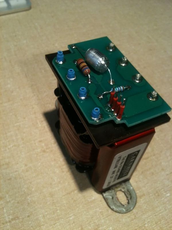
Connects with 4 little wires, with a clamping barrier block.

This is visually documented briefly in the video on the don classic site.

You need to put 4 little short wires on the output transformer board.  These bend to the right a bit to the when the transformer slides in, you can see this in the video a little. If you cut the wires 11mm long it works well (mine extend 9.5mm above the circuit board top)

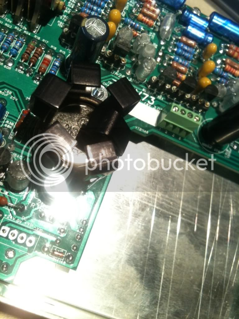
Also, in my case the 4 lower (left hand in the installed module) terminals on the output trafo are in contact with the bottom of the board (it is touching on one of my units, on the other nearly touching).  And that section of the board has a 48V phantom trace running in it.. so I insulated the terminals with shrink wrap in case the soldermask wears through someday.  See cute little blue hats in the picture.

output.jpg


Input Transformer

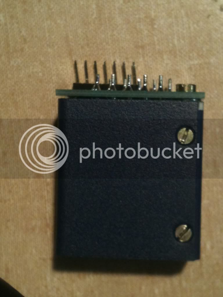
Connects with a 7 pin header to a clamping barrier block.  The BOM calls for a longer pin than is needed but standard ones are a bit short you need about 8.7 mm to 9mm above the top of the board, and I used some that extended 8.7mm above the board and it worked well.  I found I had to shift them all a bit to get good alignment.  I also put a think washer under the board and it's single screw, to avoid the stress of tightening that screw and flexing the board against the pins.

I am not sure I like the pins, they are in the video, but I would not recommend them. While pins are copper they are very hard and square, and when you tighten the barrier block they don't feel like they deform, so I am not sure it is a reliable connection.  If I build another I might use 7 pieces of wire instead.  The barrier block seems to depend upon some amount of deformation in the wire to make a solid connection, and I worry these will loosen.  This is just a feeling (when you tighten them down instead of that mushy crushing tightness, they sort of stop dead, and it doesn't feel like you can get any tension built up on the screw or you might bust it).

input.jpg


Heatsink
If you bend one wing of the heatsink, it will not come in contact with the output transformer.

heatsink.jpg


Pushbutton Switches
I snipped a tiny bit (64th of an inch?) off the bottom of the pushbutton supports because they seemed a hair high.  They are very well centered now, but they are sort of loose switches so it probably doesn't matter if you don't do that. The key thing is to install the caps with just one point soldered, so that they can be visually aligned (they are long rectangles and any misalignment is obvious (to me)).


Any idea for nice knobs for this?

Have to go run audio through these.
 
In the white market, there's some imitation red neve knobs that are made of metal that looks pretty good.
http://www.groupdiy.com/index.php?topic=45767.0

The ones I am using dont look that bad  :)
 
I've A Can I

Thanks!

Yes yours do look good.

I ordered some of those red knobs just now...  I think they will work great (I am going to try to fit one of the classic api small aluminum ones on the bottom output pot).

I would love to know if I could get the metalwork carrier for this module .... It is such a nicely made and versatile carrier (because it has ways to mount heavy transformers and extra cards, I think it could be used for custom modules as well.

Which is probably another thread .. but we really propose a "standard" for hole placement on the carriers and cards, and put out an eagle file with the edge connector and holes that would work as a PCB for that.  This could enable more folks would be able to publish and produce some of these custom modules.  Working out dimensions, gold finger plating, metalwork, carriers and hole sizes is a bit of work... (I am trying to do it now) and a wheel that really doesn't need to be re-invented.

 
bruce0 said:
I've A Can I

Thanks!

Yes yours do look good.

I ordered some of those red knobs just now...  I think they will work great (I am going to try to fit one of the classic api small aluminum ones on the bottom output pot).

I would love to know if I could get the metalwork carrier for this module .... It is such a nicely made and versatile carrier (because it has ways to mount heavy transformers and extra cards, I think it could be used for custom modules as well.

Which is probably another thread .. but we really propose a "standard" for hole placement on the carriers and cards, and put out an eagle file with the edge connector and holes that would work as a PCB for that.  This could enable more folks would be able to publish and produce some of these custom modules.  Working out dimensions, gold finger plating, metalwork, carriers and hole sizes is a bit of work... (I am trying to do it now) and a wheel that really doesn't need to be re-invented.
Igor has a metal enclosure coming out which can modularly expand to fit modules accordingly. He also has the rackit 2 coming out as well. Maybe send him a message to see if it fits your needs.
 
canidoit:

Sorry... I don't want to hold modules in carriers.

I want the actual Carrier itself.

Classic Api has an L-Bracket carrier but... 

But the great thing about the metalwork on this NV73 module beyond the obviously high quality is that it is more than an L-Bracket.  You can hang transformers from it, it would be pretty easy to enclose it entirely, and you could screw a small L-bracket on the transformer holder to hold another card layer (instead of standoffs, which can not be retrofitted if the screw holes are not already there).

Jeff Steiger at ClassicAPI  has shown some "full metal jacket" module carrier on another groupdiy.com thread which looks nice, but I think he is doing it for his own modules.

What I want is a "standard".  Something to help more folks make more modules in the 500 format. 

One great thing about 500 format is the ability to experiment with circuits and use them in actual work, to gain real world experience with them, all without the "becoming a machinist" (to quote Scott Hampton), and building power supplies for each project.

This could all be a lot easier if there was standard.  Lets call it the GDIY 500 Carrier Standard.  It would have :

1) A "tried and true" tested with a board house (EAGLE?) part footprint for a 500/51x Card, with edge connector and all the little jumper holes, and 51x mount holes with nothing else.  The card would be .06" short for the thickness of a carrier.  The card could also have shallow notches in the edge to allow for a carrier that folded up around it to carry screw mount transformers or other "layers" of board.

2) A carrier, drilled with that SAME hole pattern.  It would have an L Fold to face the front panel.  It would also have side Folds top and bottom (probably not full length though) to allow for mounting components. Front face would not be drilled (too many options) and Top and bottom would also be un-drilled.  But mount holes for the main card would be drilled.

Using that standard, anyone could draw a schematic, lay it out and be able to get a module made, only worrying about Front Panel and Circuit.

Clearly there are lots of folks making 500 series kits and boards at various levels.  Some really nice ones.  Bruno, Jeff, Gustav, Volker, Igor, Don, Colin, Owel and others.  Each has his own bailywick and  it is understandable that they don't publish the eagle part.

It would be nice to lower the barrier to  "regular hobbiests" (obsessives) to do modules in 500 format without "remeasuring" the wheel and building a metal shop.

Maybe if a standard existed, and was used, someone of the "businesses" would offer a pre-drilled carrier.

 
No I havent turned it on yet, these are recommended steps before turning on the unit for the first time. But I am not gettting reading expected between grounds
 

Latest posts

Back
Top