Official C12 Clone - Build and Support Thread

GroupDIY Audio Forum

Help Support GroupDIY Audio Forum:

This site may earn a commission from merchant affiliate links, including eBay, Amazon, and others.
We have lift-off! I moved the backplate connections to another point on the capsule and I replaced C13 with a polypropylene orange drop which I was a little hesitant to do because of urban legend as to the quality of those when used in an audio path but it sounds fine. I also redid the grounds on the cable to the power supply. The thing that puzzled me most was low level noise about 50db down from signal I was getting but had a difficult time pinning down. Now this is a little embarrassing but turns out it was the cooling fans in my Pro Tools PC in a rack about 8 feet away. Now I build these PCs for studios and pride myself in building an exceptionally quiet PC for my customers. It just so happens that this mic is so sensitive it was picking it up exceptionally well. The quietest room in our home is our master bath so that's were I put the mic stringing mic cables through the house and talked my wife into singing a bit, hi pass filter on my Avid Omni did the trick for what little air conditioning noise there was and I'm golden. The top end on this mic is brilliant to say the least and I see no lack of bottom end whatsoever with the stock .56uf output cap.

The donor power supply for this was from an Apex 460 that a friend and I modified years ago, the Apex 460 mic itself has a Peluso CEK-89 capsule and a Cinemag CM-2480 output transformer. I will probably redo that mic  P2P with the circuit from this guide and have the ability to swap mics as to need until I can build another power supply. I have a Hammond 269AX  250V C.T. 115ma /6.3V 2A  power transformer somewhere around here I can use for that. Another project I don't really have time for but that's life. Also need to get a Gotham cable for this mic at some point.

Thanks so much for the guide and the help!  8)

 
[quote author=liquidfuzz]
How is the board on the power supply grounded? I dont think i saw any notes on that...
[/quote]
What do you mean, "grounded", exactly?

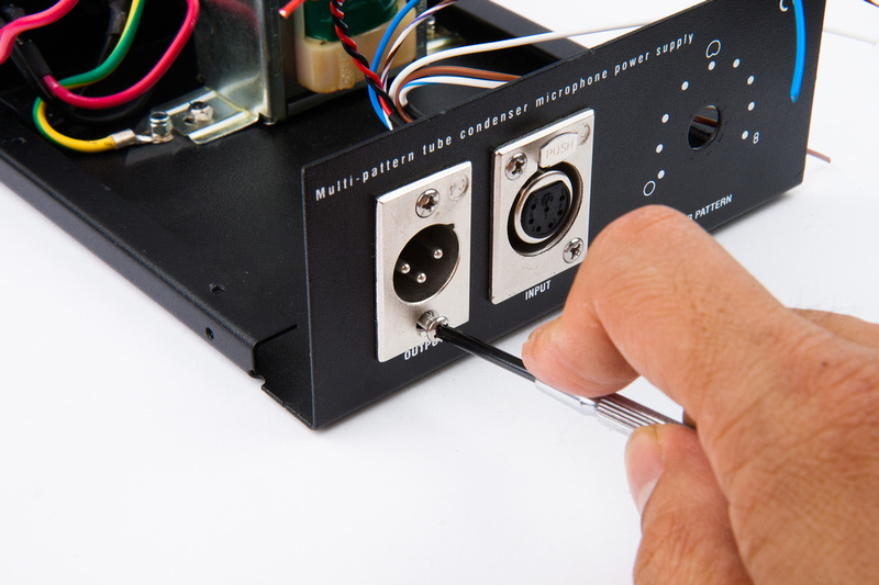
I'll take a guess:  if you mean how does the PSU 0V get tied to earth safety ground?  It's a bit hard to see, but the chassis is tied to earth by a large striped yellow/green wire that comes installed by the factory:

p1433782500-4.jpg


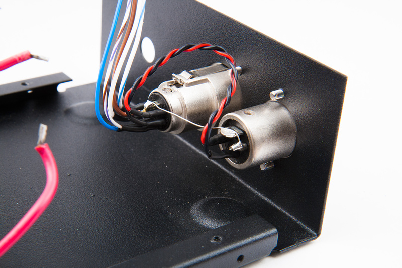
PSU 0V is tied to chassis using the wire bridge you can see between the 3-pin and 7-pin connectors:  pin 1 bridges to the metal shell, which jumps over to the 7-pin connector's pin 7, which is also tied to the 7-pin connector shell:

p1433782978-4.jpg


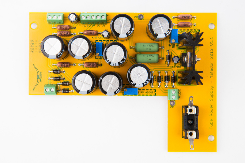
If you don't like to do it that way, there is a small 0V pad right next to the 9.5VAC connector (also right next to the fuse):

p1433780912-4.jpg


You can jump that directly over to the earth bolt next to the power transformer shown in the first pic.
 
I wired a temporary ground to the circuit to measure bias, filament  and B+. It seems to fire up nicely. I just have one question. What's the spec for B+ in this circuit (referring to the v1.4 PSU). In my build B+ sits at 200 Vdc, unloaded.
 
liquidfuzz said:
Aha... But why ground via the chassis?
To be specific here, let's distinguish between circuit '0V', 'chassis/shield', and 'safety earth'.

The stock implementation (from Alctron) is trying to balance between noise immunity and ground resistance:  the stock circuit joins circuit 0V and chassis/shield (right at the 7-pin connector, and again at the microphones output connector) in order to minimize ground resistance.  This is the way it's set up stock from Alctron.

The "best" implementation (conceptually) is to ensure that circuit '0V' only returns to the PSU via the 7-pin cable pin 7:  the microphone's pin 1 should be bonded to the shell of the microphone body (via it's retention bolt), and chassis should be bonded to safety earth at the single point where the safety earth attaches to the chassis.  The PSU's XLR's pin1 and shell(s) should be bonded directly to the chassis where they exit the PSU.  Then, circuit 0V should return to the earth point so that the chassis and circuit 0V don't drift too far apart (which is better for noise).

However for a given microphone in a given environment, having the shield return circuit 0V (by tying chassis and pin7 of the PSU connector) can actually be less noisy for a host of reasons:  for example, return impedance of 0V can be much less when you factor in the cable shield and body shield go in parallel with the 0V ground wire.  However with DC heaters, I never noticed much difference either way.

liquidfuzz said:
I wired a temporary ground to the circuit to measure bias, filament  and B+. It seems to fire up nicely. I just have one question. What's the spec for B+ in this circuit (referring to the v1.4 PSU). In my build B+ sits at 200 Vdc, unloaded.
What is a 'temporary ground'?

Unloaded, it could be anything.  Earlier in the thread we describe using test resistors inserted directly into the output 7-pin XLR connector:  use a 180K for B+, and 20 Ohms, 2W for the heater.  This will allow you to trim for 120V for B+ and 6.3VDC for the heaters without using the microphone at all.
 
Temporary = lasting for only a limited period of time; not permanent. I needed a ground reference during the build of the power supply. 

Thanks for the suggestion to use a dummy load and suitable specs. Not sure I have a 2W 20 ohm though, I might have some bigger resistors that will do in parallel. Is the B+ dropping some 80V, i.e. from 200 to 120Vdc?  A ~80V drop would actually make me very nervous, If you hadn't told me. Thanks!

 
A little problem in my recent built.

This week i've built the c12 clone using my Apex 460.

I retained the capsule (dont have the money to change now) and the transformer (it was pretty linear and usable) and i'm using a RCA 6072 tube.

Everything went smoothly. Adjusted the supply heater, bias and +B as per description (6.3v, -1.00, +120v) without any issues.

On the mic itself I got 6.1v, -0.8 and +119) not too far from specs.

But the output volume was very low.

So I thought it could be the low +B compared to the original. The original circuit i think worked around 190v, so I altered the pots to get 6.3v on the tube (6.5v from PS), and went to max I could get from the PS (152v), receiving around 150v on the mic itself.

The volume improved a lot, but still a 'quiet' microphone. Should work fine on drums but not for all types of vocals.

Am I doing something wrong?

I have a signal generator and a osciloscope to test.
 
Oh is this the Facebook question?

As I said there:  inject a 0.2V peak-to-peak signal into the grid of the tube, and measure the output between pins 2 and 3 of the output XLR.  You should see approximately 6-8dB of overall voltage gain (meaning roughly 0.5V peak-to-peak).

Do *not* raise B+, because you can destroy capsules (but the tube won't care).
 
Matador said:
Oh is this the Facebook question?

As I said there:  inject a 0.2V peak-to-peak signal into the grid of the tube, and measure the output between pins 2 and 3 of the output XLR.  You should see approximately 6-8dB of overall voltage gain (meaning roughly 0.5V peak-to-peak).

Do *not* raise B+, because you can destroy capsules (but the tube won't care).

Lol, yes, it is the same as the facebook. Didnt know you were in that one too. Sorry for the repeated question.

I injected 1khz at 0.2v and got around 0.55v. So i guess it is normal. I guess I need quieter and louder preamps. Thanks for the support!
 
What kids of recording situations are you experiencing?  Are you distance miking quieter sources?  There are a few ways of squeezing more gain if needed, but it requires circuit changes.
 
Matador said:
What kids of recording situations are you experiencing?  Are you distance miking quieter sources?  There are a few ways of squeezing more gain if needed, but it requires circuit changes.

I just tested with my voice. no 'real' source yet. But i'm not quite the singer. I will do further tests and update. thanks for the attention.
 
Hi all,

I built a MataChung C-12 back in 2013, and am just now gearing up to build a 251 using the V1.4. In looking at post #1, there are links listed for both the V1.3 and V1.4 schematics but they both appear to link to the V1.3 .pdf. Is there a V1.4 schematic available somewhere?

Thx!

AJ
 
ajemutt said:
Hi all,

I built a MataChung C-12 back in 2013, and am just now gearing up to build a 251 using the V1.4. In looking at post #1, there are links listed for both the V1.3 and V1.4 schematics but they both appear to link to the V1.3 .pdf. Is there a V1.4 schematic available somewhere?

Thx!

AJ
V1.4 is more of a PCB thing, not a schematic thing.  The head amp is identical (and still says 1.3), however there are some BOM changes in the PSU (notably R1 and R2).
 
Matador said:
V1.4 is more of a PCB thing, not a schematic thing.  The head amp is identical (and still says 1.3), however there are some BOM changes in the PSU (notably R1 and R2).

Thanks. It looks like at least  R1,R2,R6, R9,R10, don't match. I'm not experienced enough with circuits to know if - in the case of R6 for example, there really is a difference between 499k, and 470k, so I'm going around in circles a bit trying to sort this out.

Making the process a little more confusing, I also seem to be missing a few PSU resistors, and have some that don't correspond to the board or schematic -  a couple 33.2k, for instance. I suspect that I got an incorrect baggie mixed in with all my parts. I'm gonna send a PM to Chunger in a min.

On other note/question about these resistors, most of the PSU resistors I received are carbon, and not metal film. Looks like this build has always used metal film, but the Universal PSU build does show carbon in the guide pix (the resistors I got don't entirely correspond to those either). For the PSU, is there a performance difference between metal film and carbon?

thanks!

A
 
Hi, I'm near completion of my C12, and am getting around to putting an RK12 microphoneparts capsule in it. I've tested the mic with the stock parts and everything worked great. I've swapped a five star 6072A in, and just wired up the RK12, so now for the nail-biter moment where I don't want to blow anything expensive! 

Does anyone have any experience with the proper B+ setting on the power supply for these capsules? Matt at microphone parts, who wasn't familiar with the circuit, recommended they receive 60V. Judging by Mr. Campbell's description of how voltage arrives at the capsule (FC to ground, 60 to BP, variable voltage to RC), am I correct that 120 would be the proper setting for the RK12 as well?

When I attempted to set the B+ to 120 in anticipation of connecting the capsule, I found that my trim pots didn't let me go below 182/3. A clicking sound seemed to indicate it had gone the lowest it can go. Any advice? Don't want to blow a capsule, I love my RK12!
 
Capsule polarization is a 50% resistive divider from B+, so if set to 120V you get 60V on the backplate.

The actual capsule doesn't play into the voltages:  if you trim it out with capsule A, capsule B will 'see' the same voltages.
 
Hi Matador.
In populating the power supply board (V 1.4), there's an extra terminal block not in any of the photo's (sits next to the 5 connector terminal block) and the board marks it "Heater" and "Ground". Not sure what to connect there...

Thank you
Geek
 

Latest posts

Back
Top