Official C12 Clone - Build and Support Thread

GroupDIY Audio Forum

Help Support GroupDIY Audio Forum:

This site may earn a commission from merchant affiliate links, including eBay, Amazon, and others.
Spencerleehorton said:
Hi Matador,

Im pretty sure i was just looking at the wrong psu schematic and i have 91k in the psu.
what should i lower them too?
regards

Spence.

Aye.  The best thing is to lower both R1 and R2 equally.  It looks like your tube is drawing a bit more than the expected 0.6mA at idle, so each 10K drop will yield about 50-10V of adjustment.  So if you dial R4 to until the B+ is as high as it can go (let's say 100V), then dropping R1 and R2 by 20K each will raise B+ up to about 140V, when you should be able to drop back down to 120V by adjusting R4 again.

I can help you zero in on it a bit better if you max out R4 (drop B+ as low as it will go), and tell me the new B+ voltage with all resistances at maximum.
 
Spencerleehorton said:
Hi Matador,

Im pretty sure i was just looking at the wrong psu schematic and i have 91k in the psu.
what should i lower them too?
regards

Spence.
http://www.groupdiy.com/index.php?topic=51377.msg666445#msg666445


Check this out I had a similar problem.

http://www.groupdiy.com/index.php?topic=51377.msg666445#msg666445
 
Spencerleehorton said:
Hi Matador,

as it stands i get 77v with 100k turned all the way one way and 94.5v turned the other way.

regards

Spence.

You drop ~200V across 182K with the 100K turned to zero.  You are idling at 1mA.  This is a 6072A tube?

In any case, you want 40V more which means ~40K less.  I would drop R1 and R2 down to 75K (16K each), and the pot should make up the rest to give you some room around 120V.
 
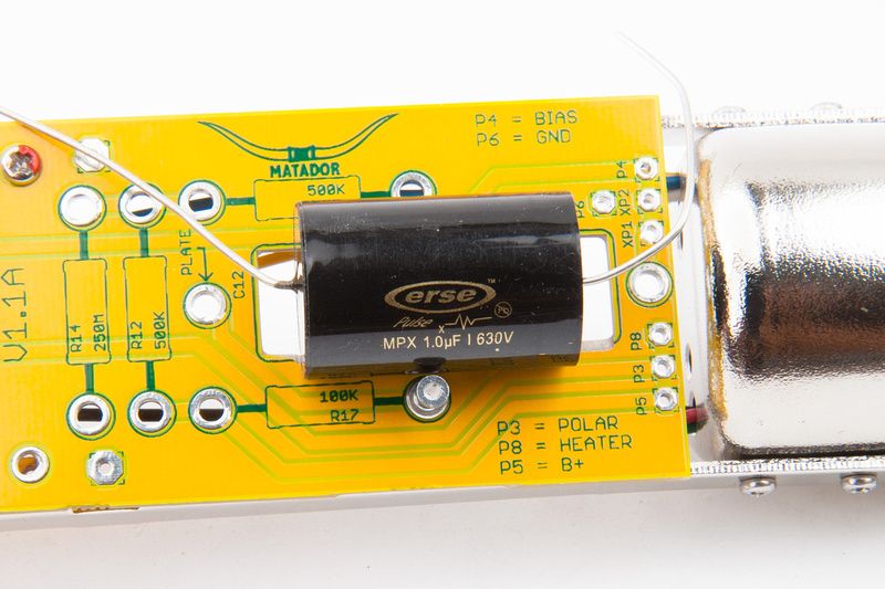
UPDATE:  Erse changed the specs on their 630V 1uF capacitors. . . . DOH!  They were out of stock for quite a few months and the new shipment is significantly larger diameter than the previous batch. . . beyond the measured interference tolerances I calculated internally for the HT-11A body anyways . . . meaning, the cap touches the tube body.  Because the rails are pretty flexible, the mic still assembled fine with the new capacitor, but I've made some modifications to the build instructions to slightly modify/file the PCB to accommodate the new kit 1uF capacitor.  Thinking to drop down to the smaller 400V version for the next batch of parts.

Also, please note that there are a large number of capacitor brands and types that fit in the provided slot besides the Erse metalized polypropylene unit that i supply with the kits.

p2022936913-4.jpg
 
Hi Matador/everyone,

All working perfectly now, voltage B+ is 120v, bias -1.0, heater 6.3v, sounds amazing!!!
thanks again, i think i have a new first choice for vocal mic!!! cuts through the mix so well!!!

regards

Spence.
 
Is anyone else using the Peluso CEK-12 capsule with their 34mm mount?

On the capsule and mount I got, the screw holes on the mount don't line up with the holes on the capsule body unless I remove one of the wires and re-insert the screw through the plastic capsule mount - thus holding the ring terminal conductor onto the body of the capsule with the mount, rather than directly with the screw.

Is this really the correct way? I'm worried that the ring terminal isn't going to make good contact unless I really tighten that screw hard, but that's just as likely to strip it out.

Any ideas on that?

Oh, another question - what's the advantage of using the pins to solder the capsule leads instead of soldering direct onto the PCB?


Many Thanks!


AJ


Hey everyone,

On the CEK-12 capsule mount, I got an email from Peluso this AM with a photo of how it should attach, so I thought I'd share.
 

Attachments

  • CEK-12 Hookup.JPG
    CEK-12 Hookup.JPG
    328.9 KB
Something interesting i noticed and I'm not sure what kind of difference it may make but in the original schematics the 6072 tube heater is center tapped to pin 9 and pin 5 is connected to ground and pin 4 is floating.

On matador circuit you have pin 4 or 5 (whatever side of the tube you are using) connected to heater with the additional pin left floating. While Pin 9 is also left floating. Is this something you consciously decided to implement?

I am going to mod heater to pin 9 like original schematic and strap pin four (on my build) to ground and see if theres a difference.
 

Attachments

  • Screen Shot 2013-09-10 at 5.00.02 PM.png
    Screen Shot 2013-09-10 at 5.00.02 PM.png
    72.3 KB
JessJackson said:
Something interesting i noticed and I'm not sure what kind of difference it may make but in the original schematics the 6072 tube heater is center tapped to pin 9 and pin 5 is connected to ground and pin 4 is floating.

On matador circuit you have pin 4 or 5 (whatever side of the tube you are using) connected to heater with the additional pin left floating. While Pin 9 is also left floating. Is this something you consciously decided to implement?

I am going to mod heater to pin 9 like original schematic and strap pin four (on my build) to ground and see if theres a difference.

I think pin 9 is connected to ground in Matadors schematic. What is interesting is in the original schematic everything that is not used, pin 6, 7 and 8 is tied to ground but the heater pin that is not used pin 5 is not hooked up also in original pin 9 is the 6.3 volt in and pin 4 references ground.
 
Pip said:
JessJackson said:
Something interesting i noticed and I'm not sure what kind of difference it may make but in the original schematics the 6072 tube heater is center tapped to pin 9 and pin 5 is connected to ground and pin 4 is floating.

On matador circuit you have pin 4 or 5 (whatever side of the tube you are using) connected to heater with the additional pin left floating. While Pin 9 is also left floating. Is this something you consciously decided to implement?

I am going to mod heater to pin 9 like original schematic and strap pin four (on my build) to ground and see if theres a difference.

I think pin 9 is connected to ground in Matadors schematic. What is interesting is in the original schematic everything that is not used, pin 6, 7 and 8 is tied to ground but the heater pin that is not used pin 5 is not hooked up also in original pin 9 is the 6.3 volt in and pin 4 references ground.

exactly… we have all been heating both sides of the tube unless you have tied everything on the unused side to ground. Looking at my tube mount there doesn't appear to be a trace from pin 9 to ground. It seems to be floating. Therefore heating both Units of the tube resulting in a 3v heater.

E.G: Say for instance you are using the right side of the tube (as per original schematic)

To my understanding, I don't think it matters where you enter 6.3v (pin 5 or 9)

  • If pin 5 injection: then you stop current from continuing to other tube side by tying centre tap (pin 9) to ground and of course all additional pins of unused side.
..
  • If pin 9 injection: then you stop current from continuing to other tube side by tying pin 4,1,2 and 3 to ground. Pin 5 would also need to terminate to ground also. (this is how original schematic does it, klaus on the other hand quotes my pin 5 injection method: http://repforums.prosoundweb.com/index.php?topic=36302.0)

Additionally the right and left sides of the tube are not identical.

The right side (Unit 1) is rated at 0.5 uuf
The left side (Unit 2) is rated at 0.38 uuf

Which is a 20% difference and I'm not nearly expert enough to comment on this area. Could this have something to do with the reason all schematics utilised Unit 1?

Attached is original tube schematic for those needing to reference it.
 

Attachments

  • Screen Shot 2013-09-10 at 6.24.07 PM.png
    Screen Shot 2013-09-10 at 6.24.07 PM.png
    21.5 KB
JessJackson said:
On matador circuit you have pin 4 or 5 (whatever side of the tube you are using) connected to heater with the additional pin left floating. While Pin 9 is also left floating. Is this something you consciously decided to implement?

I'm not sure where this is coming from:  on my build, pin 9 is grounded, and is not left floating.  You can attach either pin 4 or pin 5 (or both!) to the heater supply to light up each half of the tube (or both!).  Whatever side (pin 4 or pin 5) is left floating will definitely not be heated.

Think of the heater as two resistors, which happen to share a common node (pin 9).  So long as you put 6.3V across either pin4 and pin 9 or pin5 and pin 9, each half will light up (respectively).

If you declare pin9 as ground, then 6.3V on pin 4 or pin 5 will light each half.
If you declare pin9 as 6.3V, then you must ground pin 4 or pin 5 to light each half.
 
Matador said:
JessJackson said:
On matador circuit you have pin 4 or 5 (whatever side of the tube you are using) connected to heater with the additional pin left floating. While Pin 9 is also left floating. Is this something you consciously decided to implement?

I'm not sure where this is coming from:  on my build, pin 9 is grounded, and is not left floating.  You can attach either pin 4 or pin 5 (or both!) to the heater supply to light up each half of the tube (or both!).  Whatever side (pin 4 or pin 5) is left floating will definitely not be heated.

Think of the heater as two resistors, which happen to share a common node (pin 9).  So long as you put 6.3V across either pin4 and pin 9 or pin5 and pin 9, each half will light up (respectively).

If you declare pin9 as ground, then 6.3V on pin 4 or pin 5 will light each half.
If you declare pin9 as 6.3V, then you must ground pin 4 or pin 5 to light each half.

Hi mate, where is it grounded? There doesn't appear to be a trace from pin 9 on my board to ground. Theres no continuity unless it bridge it myself.

cheers

J
 
Is it fit a MXL V67I body? I'm asking that because they are really similar of the AKG C12 (gold headbasket and mesh, green body). Just a matter of look hahaha. Awesome work by the way
 
Looks like pin 9 runs to ground at the 2 reinforcement cut resistor leads that help hold the vertical pcb. 
It is just as matador has said...
The smd zero Olm resistor selects witch side of the triode Is used, 4 or 5 , 9 is grounded....
If your not seeing ground there, did you put the cut resistor lead gussets on tube pcb and the head amp pcb?
C
 

Latest posts

Back
Top