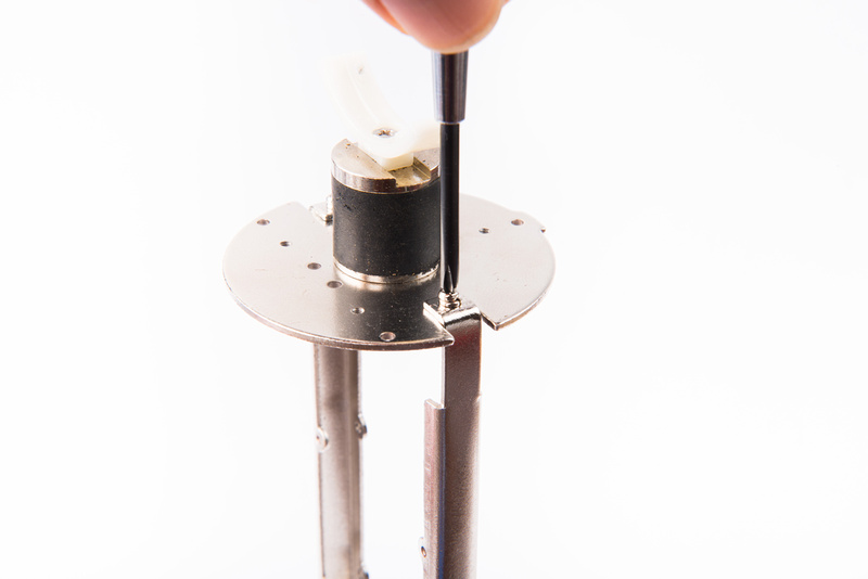
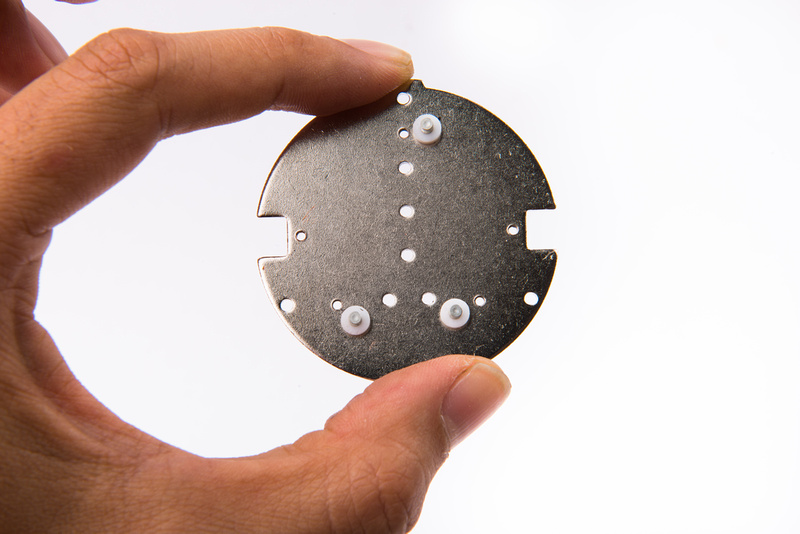
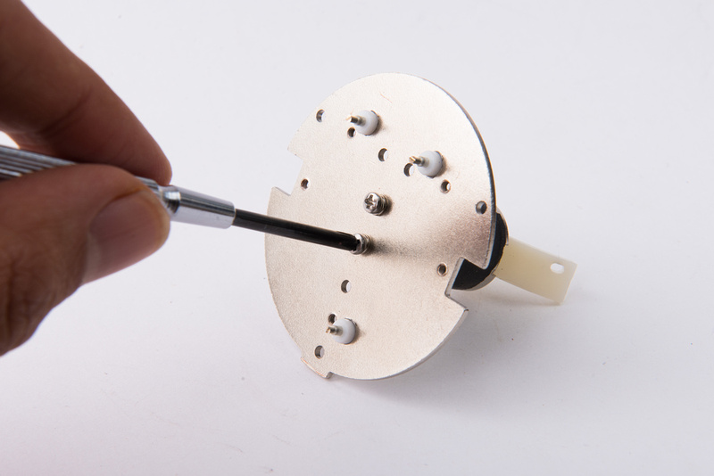
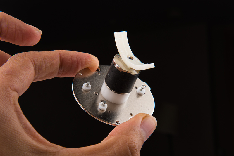
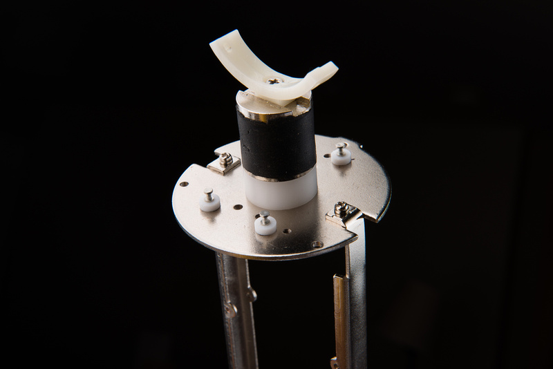
This is an optional step, but next, I prepare the chassis to install 3 teflon turrets on the top plate. I begin by removing the 2 screws holding the top plate to the frame rails and the capsule mount.
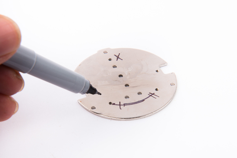
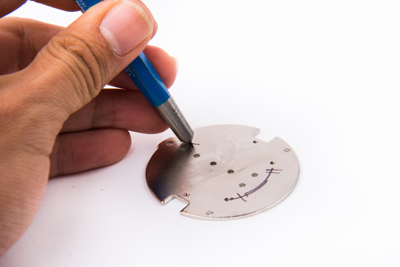
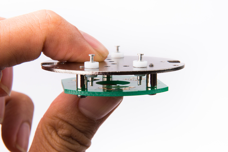
Next, I mark the location of my turret holes. It is important to consider the location of the switches that will go directly below this plate. By making my holes directly next to the standoff screws that attach the switch PCB but leaving a little space for the diameter of the standoffs, I ensure I will not hit the switches.
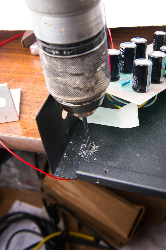
Center punch the holes and then make a small hole to start.
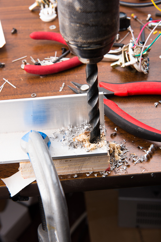
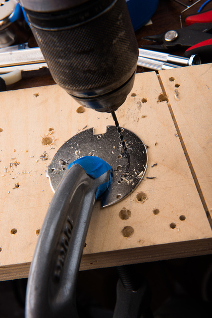
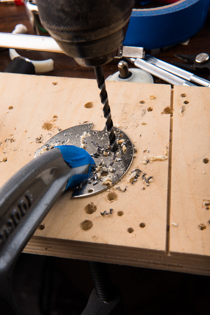
Then, follow up with a larger drill bit to fit the teflon turret.
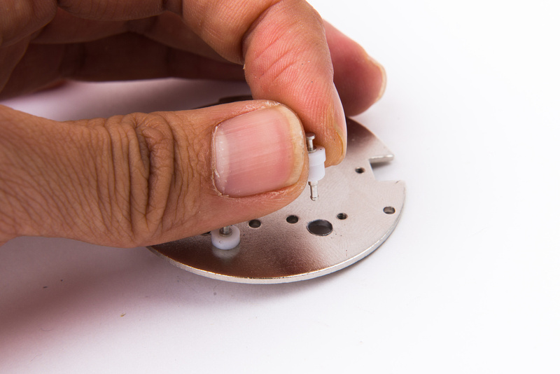
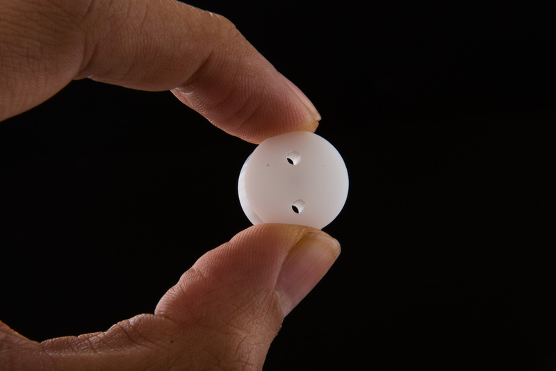
I am using Keystone 11251 turrets because they are large diameter and seem to hold much better in the top plate than the smaller turrets especially with hand-drilled holes.
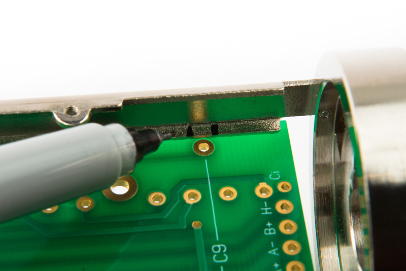
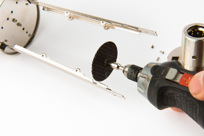
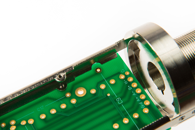
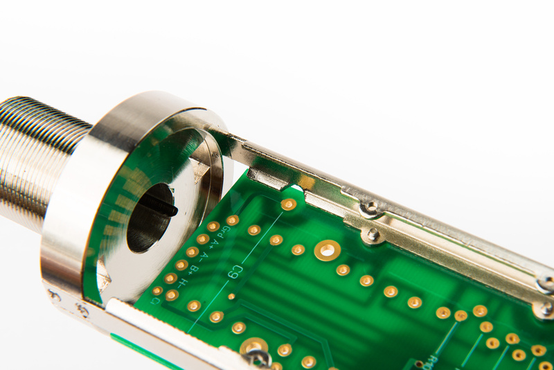
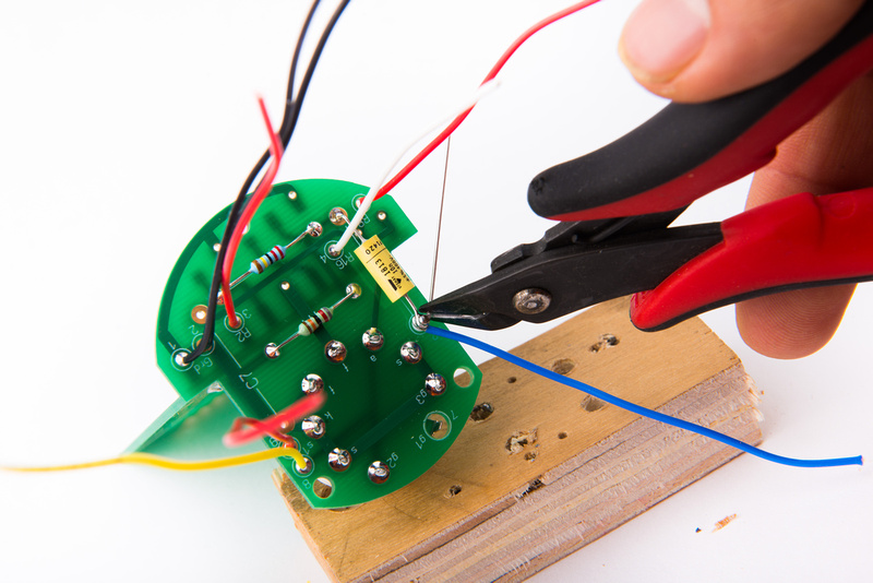
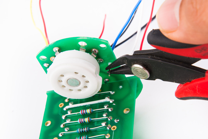
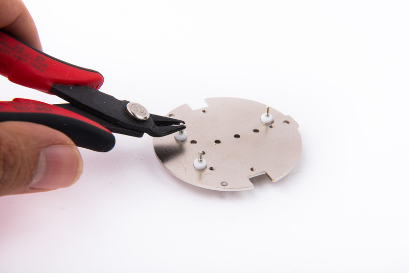
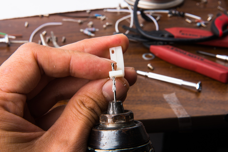
In order to clear the switch PCB, I cut off a small section of the lower turret.
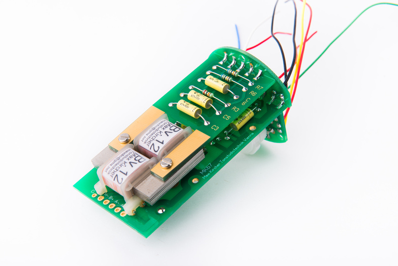
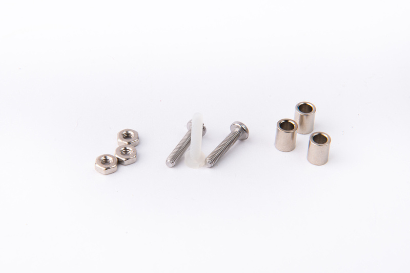
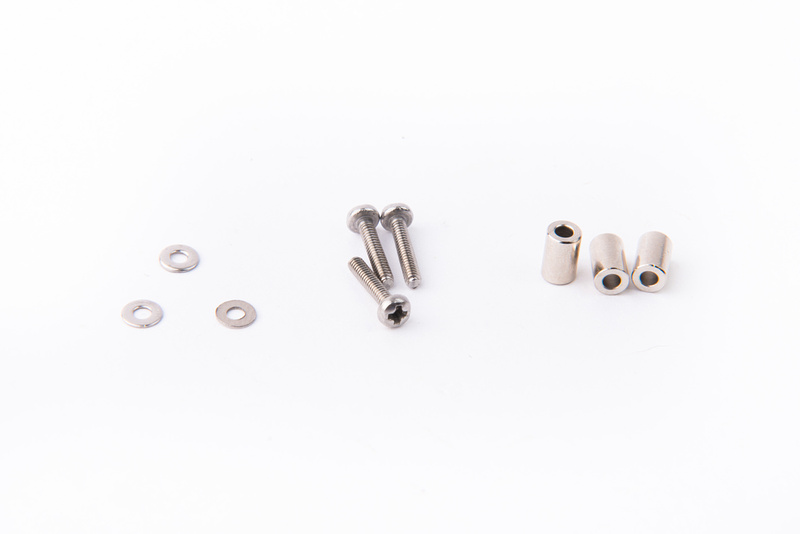
Next, locate the mounting hardware for the switch PCB. These should be included in the SYT-5 body kit.
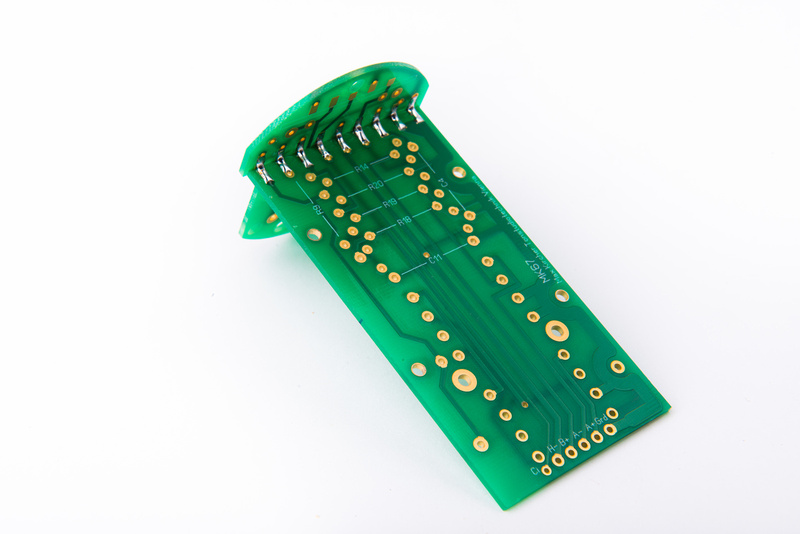
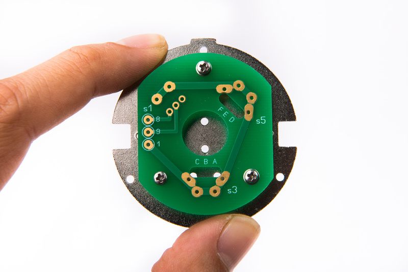
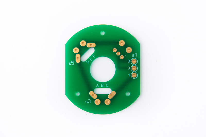
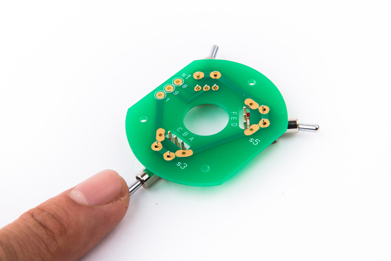
The top and the bottom of the switch PCB look very similar. Make sure you have the correct board orientation or else the switches will not match the microphone sleeve markings.
Check and make sure the turrets will safely clear all 3 switches below.
I will re-iterate that teflon turrets are an optional step. It is perfectly fine to pass the capsule wires straight through the top plate and make the necessary connections to the specified connection points on the wiring diagram directly.
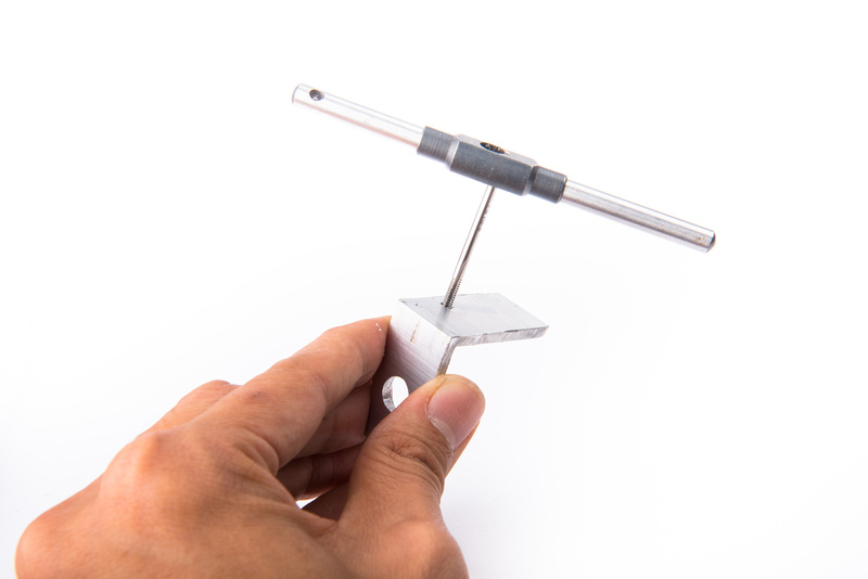
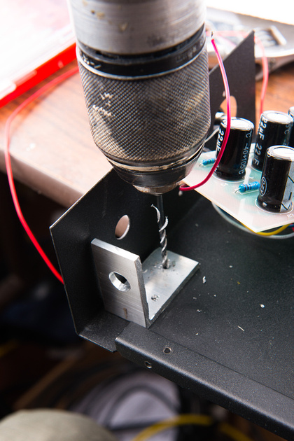
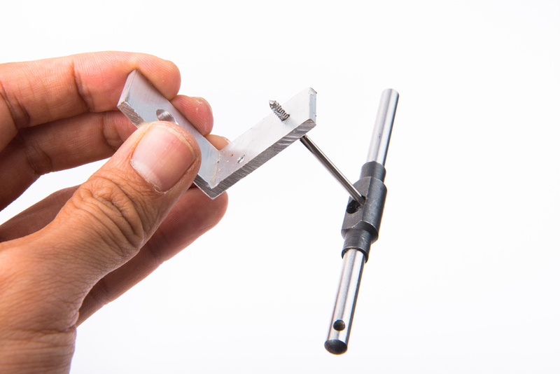
At this point with the top plate removed, it is an excellent opportunity to raise the capsule mount to bring the capsule to a more optimal position inside the headbasket. I opt to raise it 8mm. In the previous prototype, I drilled and tapped the top plate to accept the 1st Gen SYT-5 capsule mount which readily receives an M3 hex standoff to raise the saddle. For the gen 2 bodies, a spacer of some kind is the easiest way to accomplish this.
Because he happens to be local to me, I contacted forum member Shaggy who dropped by to pick up a few miscellaneous mic parts the other day and has a machine shop! I threw a quick drawing together on sketchup and he was gracious enough to produce a Delrin spacer to my specs on his lathe and drill press.
If any of you keep up with Shaggy's microphone builds
http://groupdiy.com/index.php?topic=57102.0, he is a meticulous craftsman and, well, it's a bit silly but the spacer is better machined than the entire microphone body. It's like using a Ferrari when all you need is a skateboard.
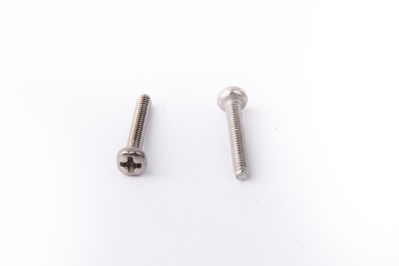
In order to insert this spacer, I will need longer M2 screws for the capsule mount. I use 12mm length stainless steel M2 screws.
With the capsule mount secured, I re-attach the top plate to the frame rails.
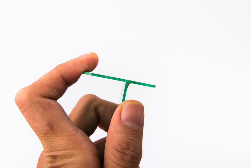
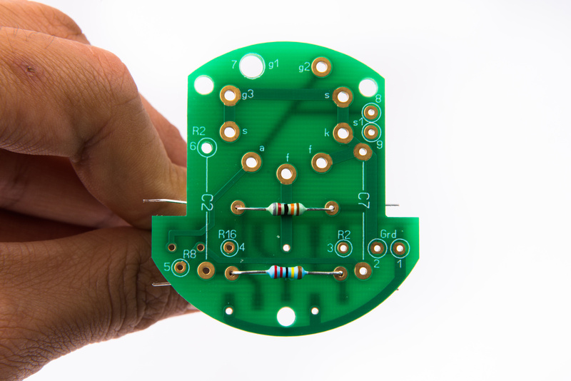
Next, install the switches on the switch PCB. The top side of the board can be identified by the lettering being in the correct order (A, B, C, - D, E, F). the bottom side will have the letter order in reverse.
Switches will mount on the top side of the PCB.
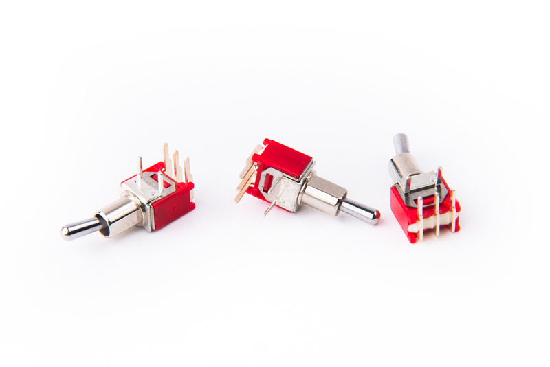
Note: S3 or the pattern switch is the 3 position on-off-on switch. The other 2 switches do not have a center position and are on-on.
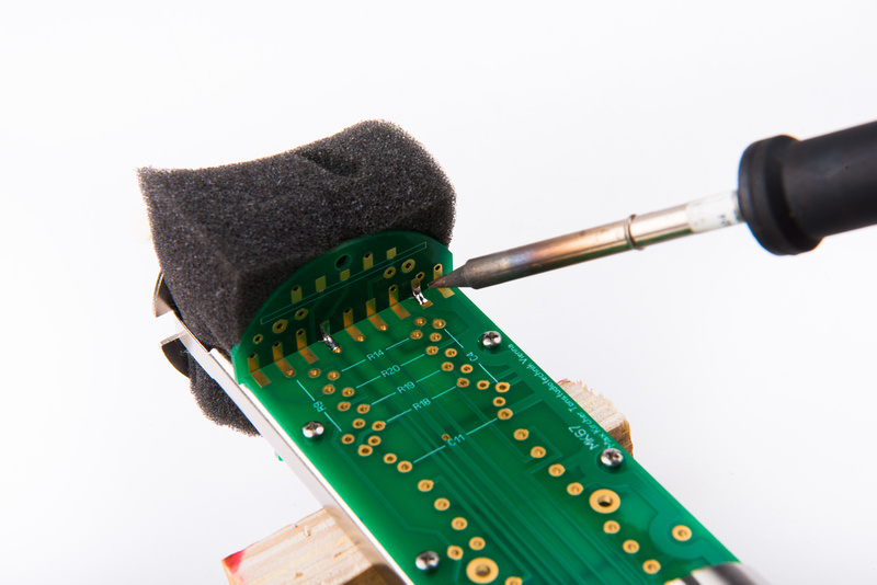
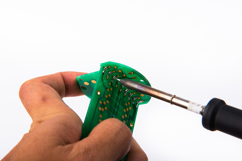
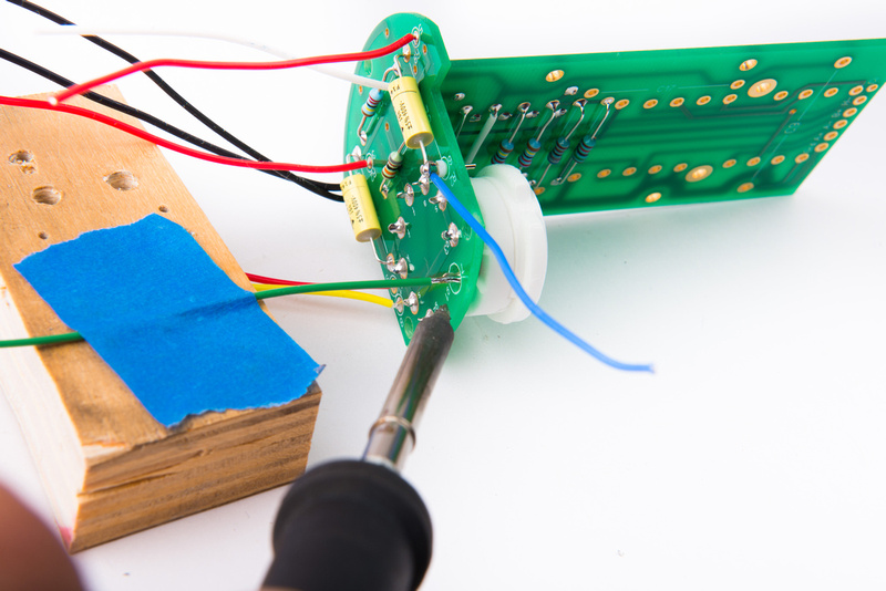
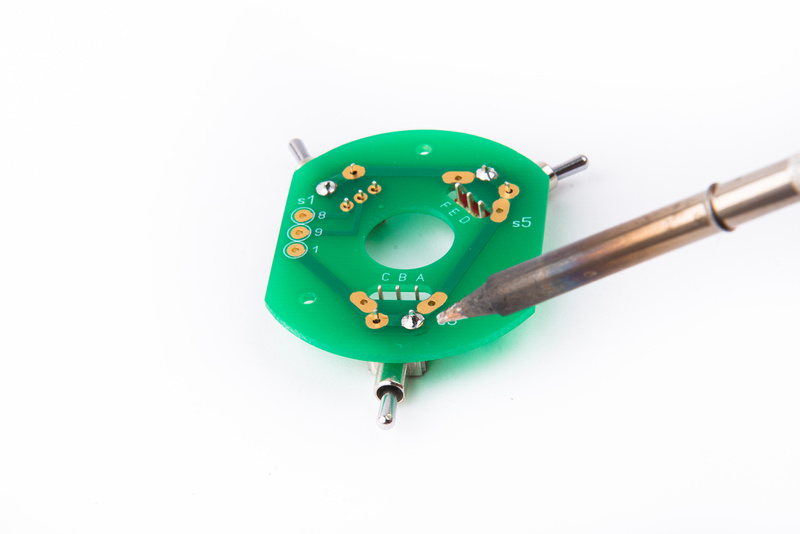
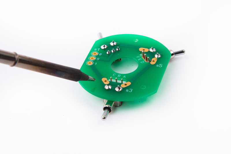
Lay all 3 switches onto the PCB and flip the assembly over to solder. The switches with the isolated contact lugs are a bit harder to align. I recommend pushing them inwards towards the center of the PCB so the 2 lugs so the switch can center on the board.
While pressing the switch towards center, solder one lug on each switch.
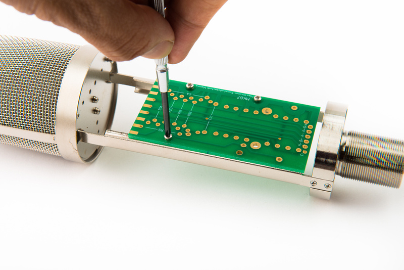
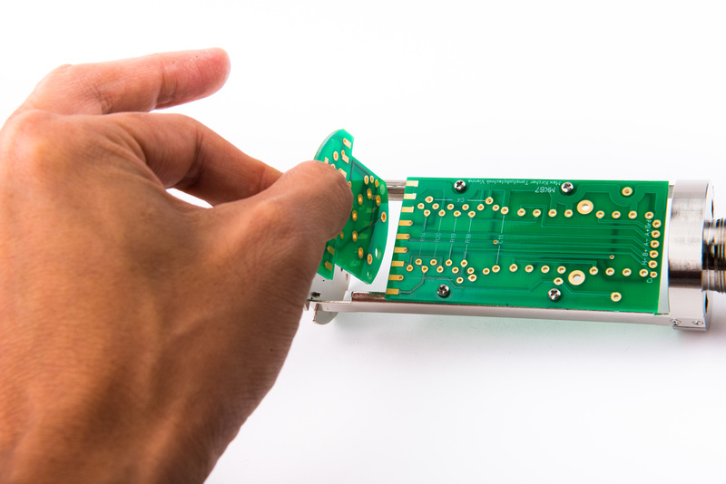
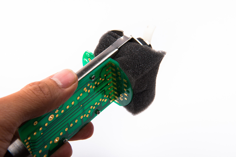
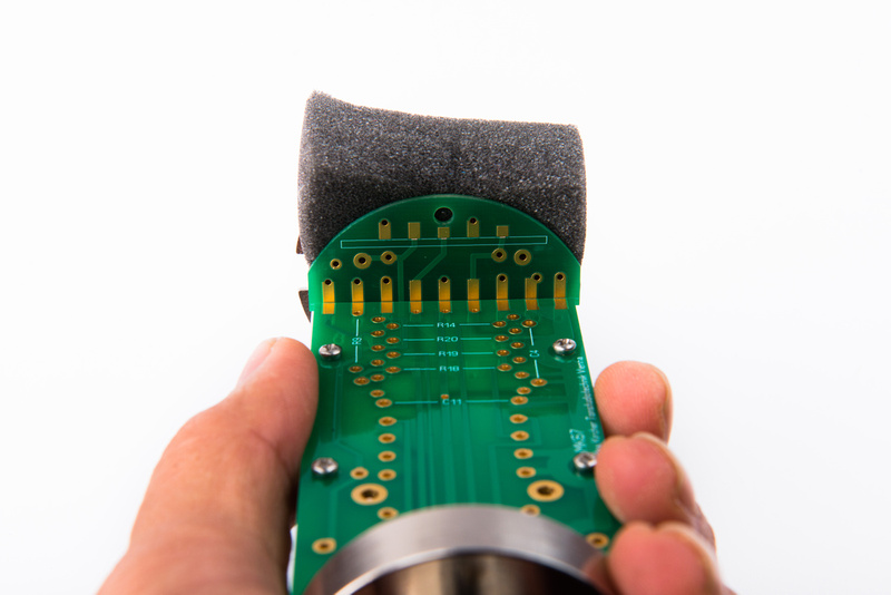
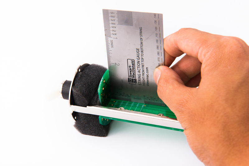
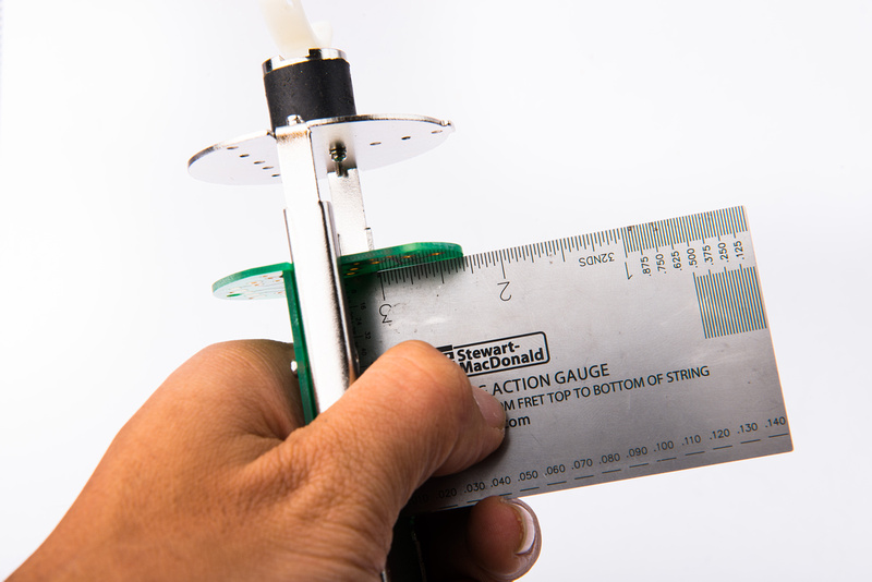
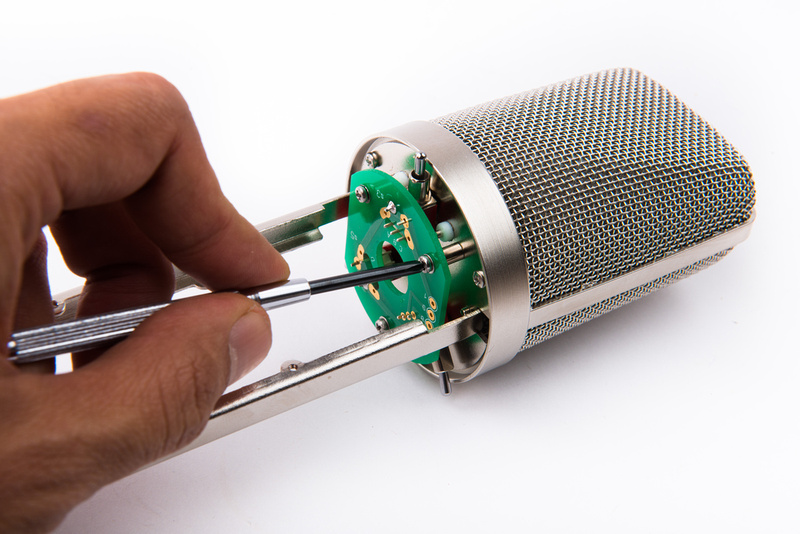
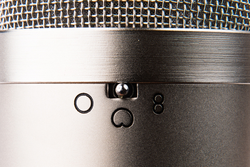
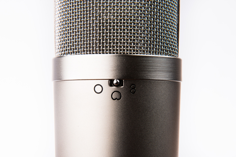
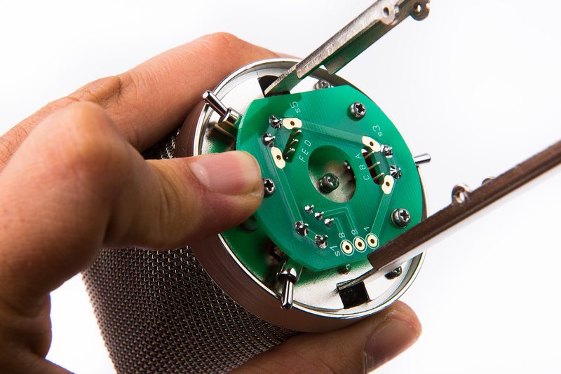
Next, temporarily install the switch PCB to check switch alignment to the cutouts on the microphone outer tube.
The 3 position pattern switch is most critical because there is the least amount of margin available for mis-alignment. Here, it is nearly perfect, so no adjustments are necessary, but if we do need to adjust, it is much easier to do with only one lug soldered in on each switch.
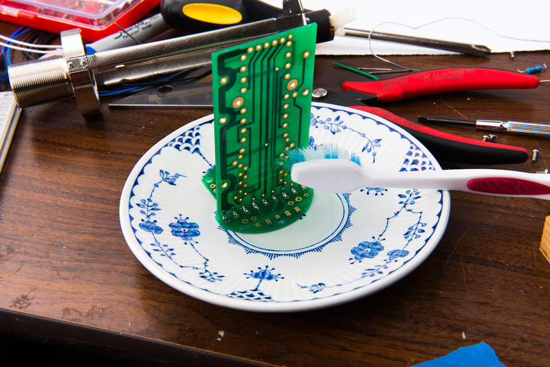
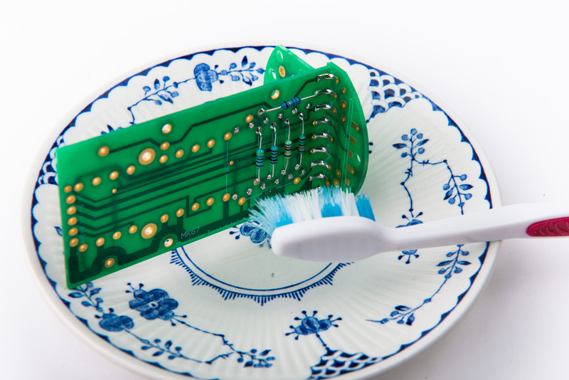
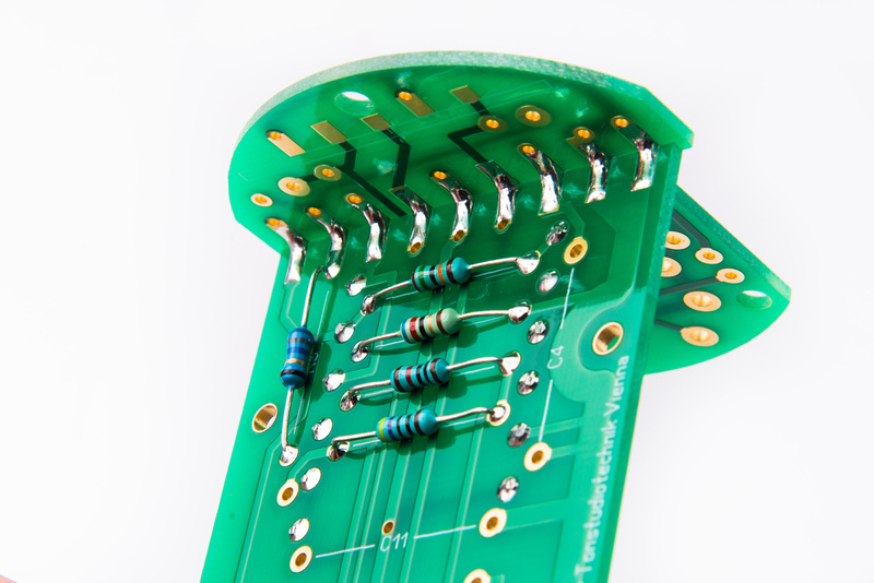
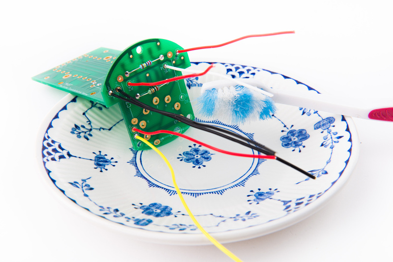
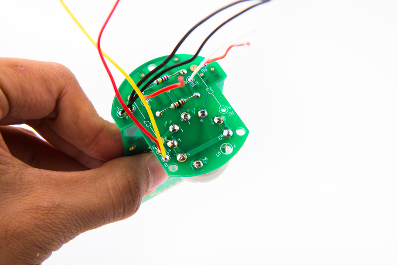
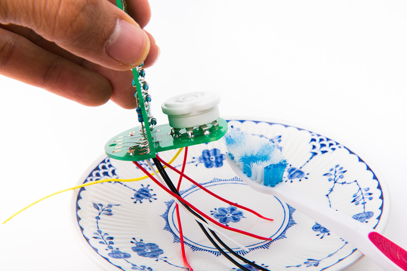
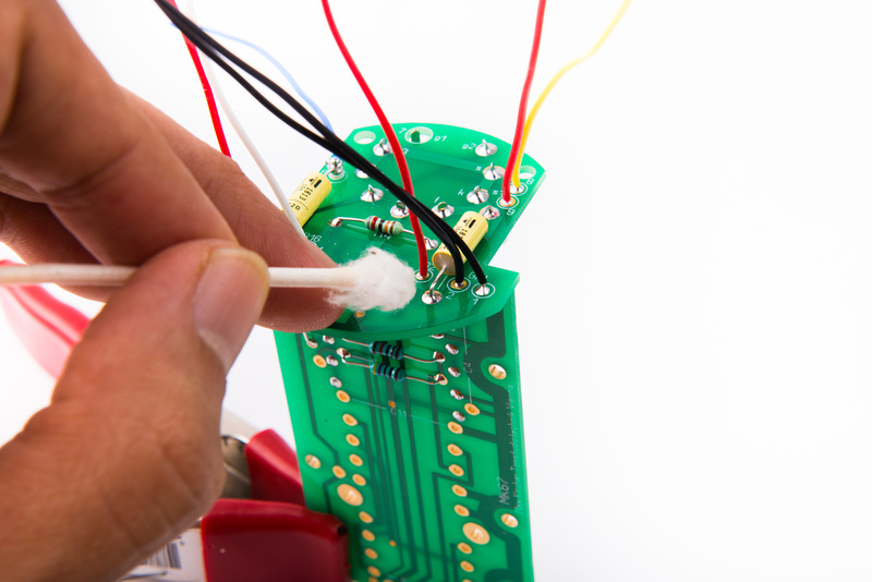
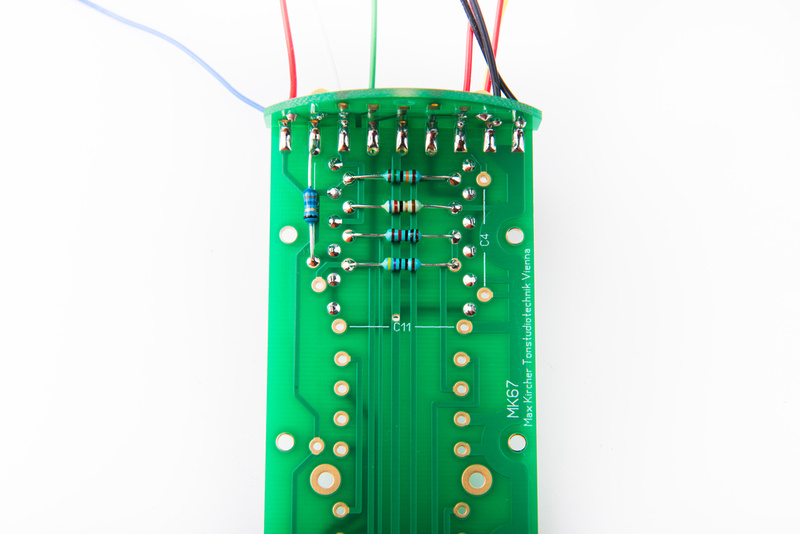
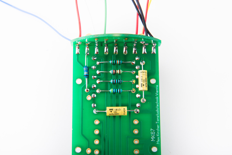
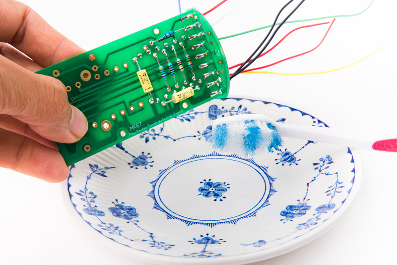
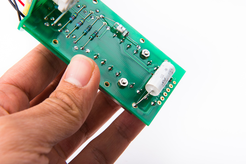
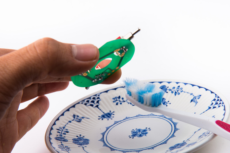
With alignment confirmed, solder the remaining lugs and clean the PCB from the bottom.
While it is unlikely the switches have shifted from soldering, I reconfirm switch alignment after the switches are completely soldered. No changes here, so we can move forward.
Note: when installing the switch PCB, a way to minimize the "slack" in the board is to press the board against the 2 screw side when tightening the screws. This will guarantee a consistent position. Also, by pressing firmly this direction, it places the 3 position pattern switch a little bit further towards the outside of the microphone which gives the shaft a little bit more room to swing.
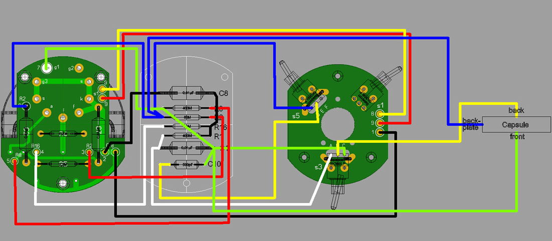
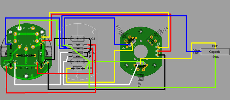
For wiring up the switch PCB, refer often to the wiring diagram in the 1st post of this thread. All of the required connections are clearly laid out there.
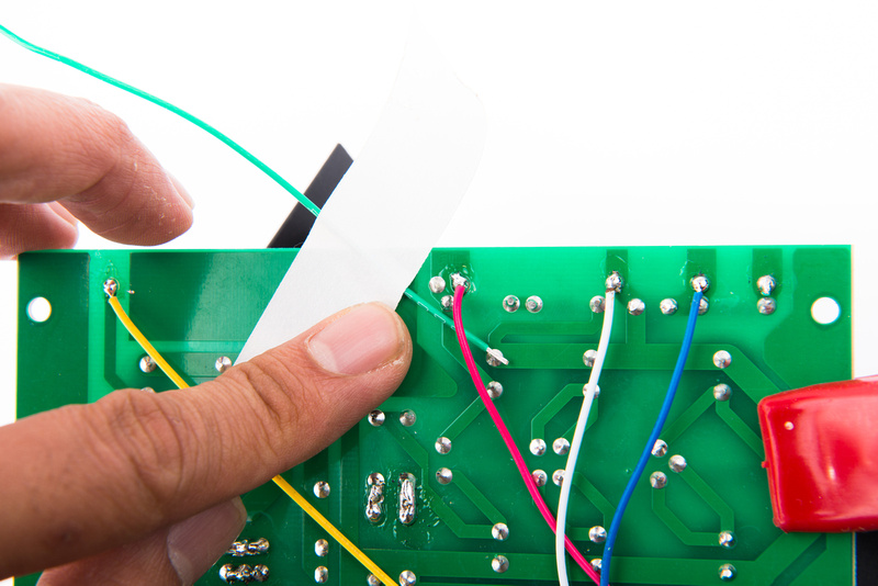
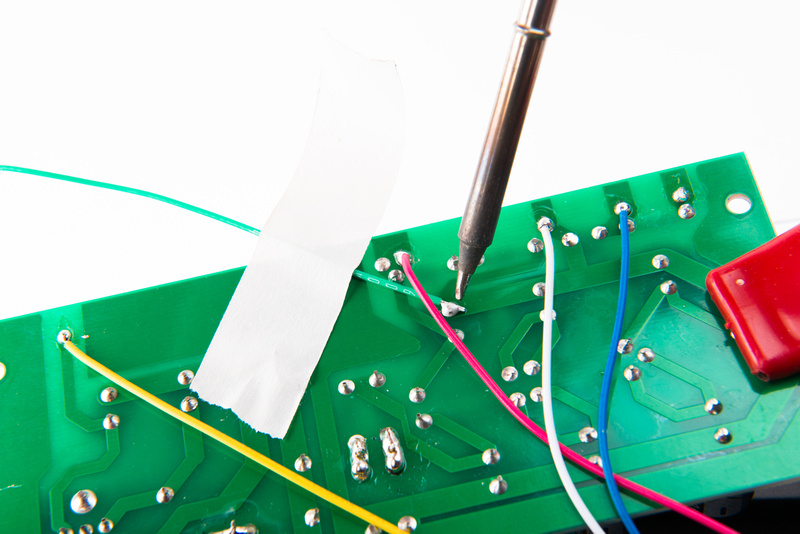
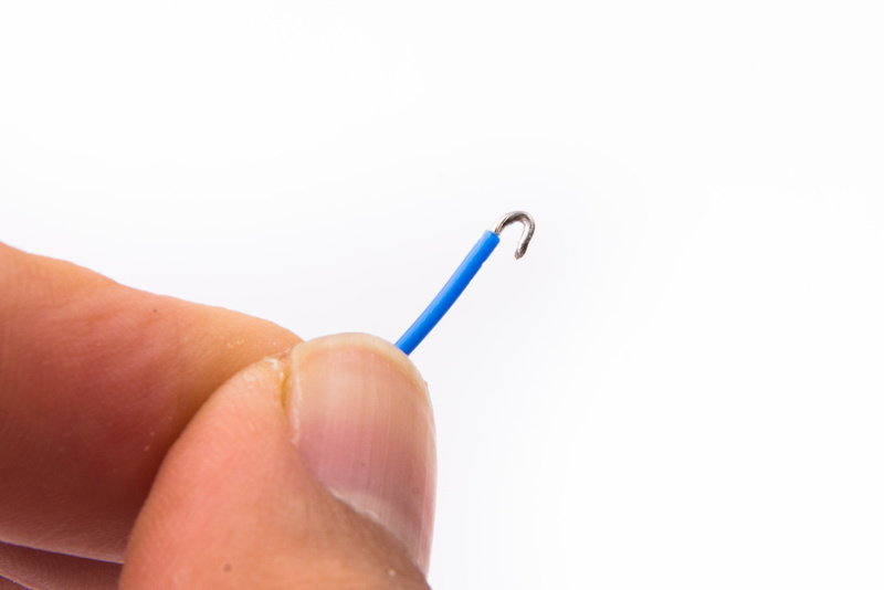
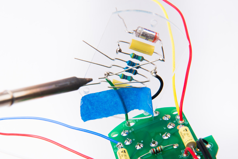
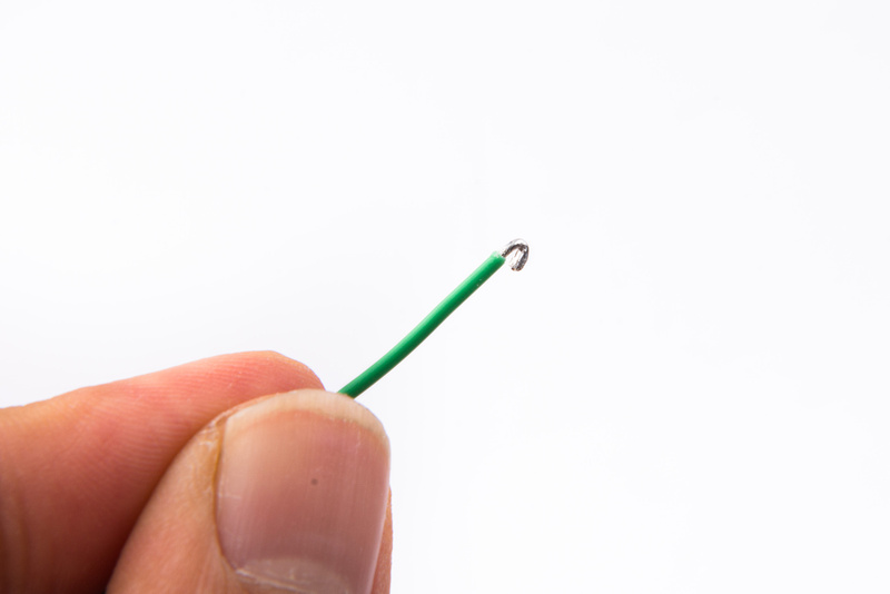
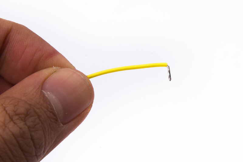
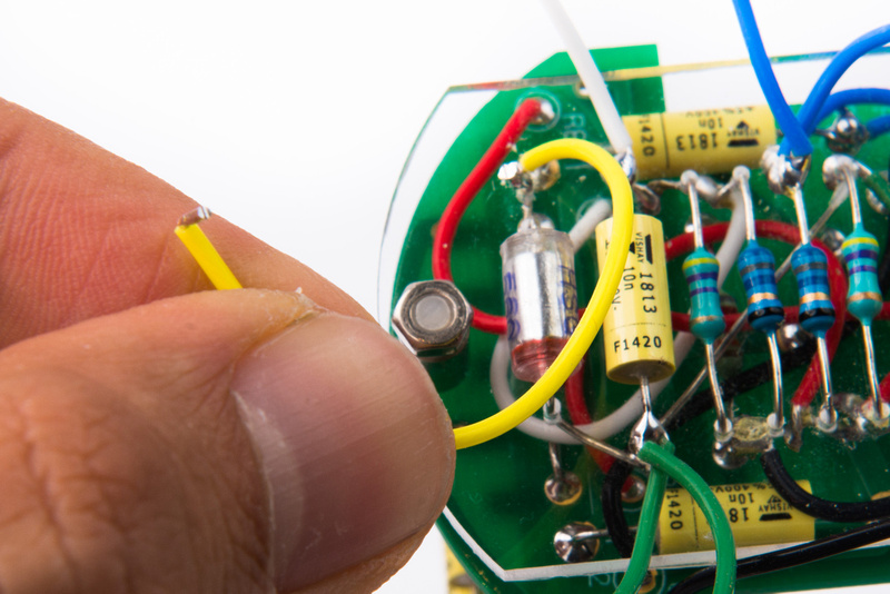
Prepare a new yellow wire by stripping the end, tinning, and creating a right angle.
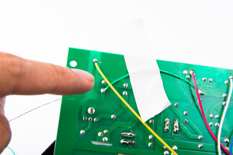
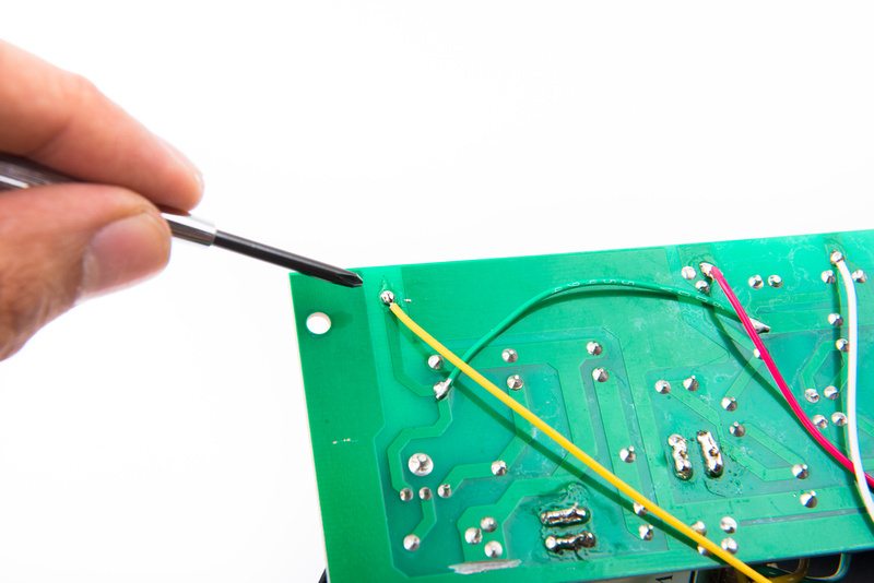
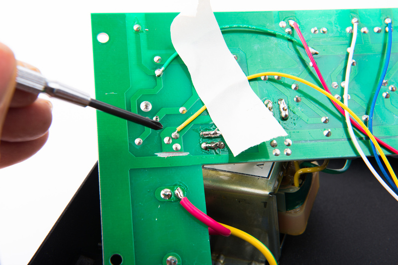
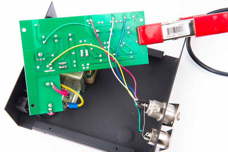
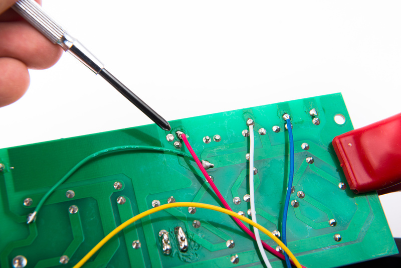
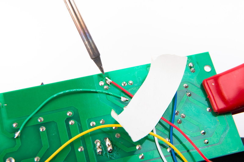
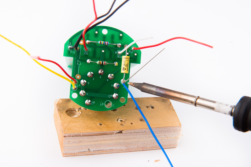
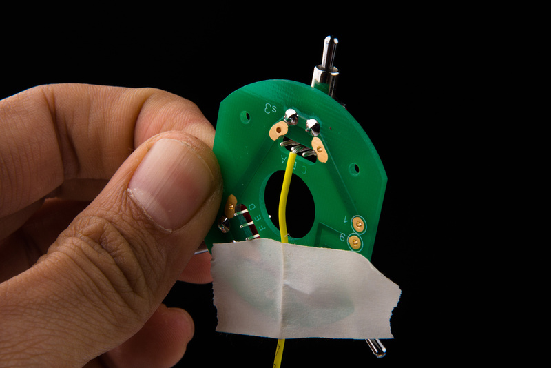
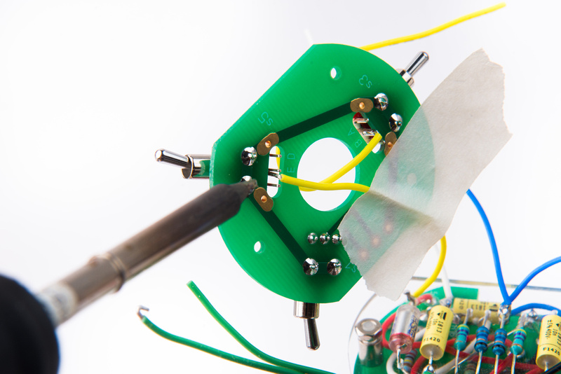
Secure the wire against floating lug "B" on the pattern switch (S3) with some tape and solder into position. After soldering, I feed this wire through the center hole as it will go up to a capsule connection.
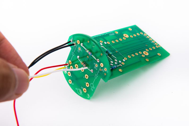
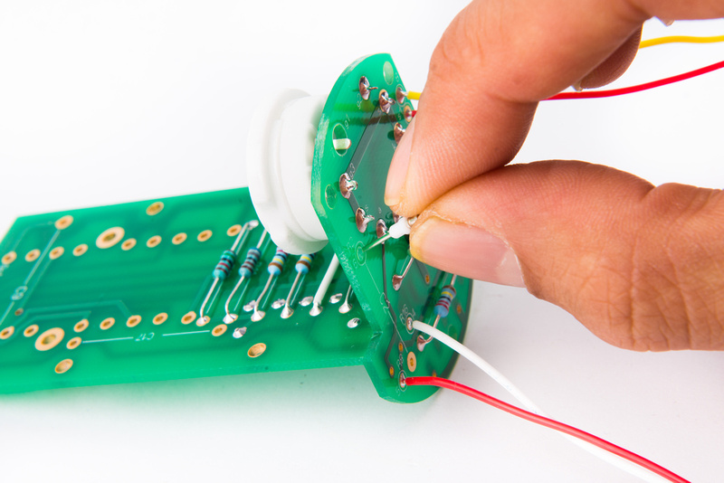
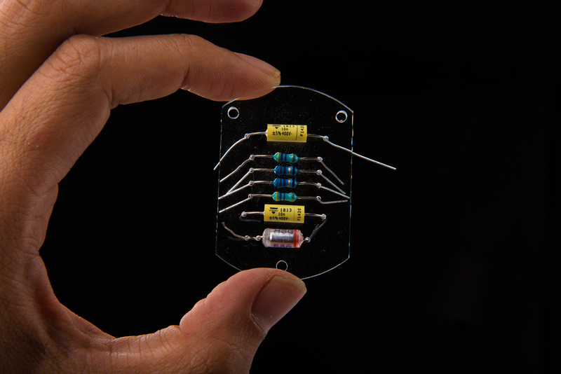
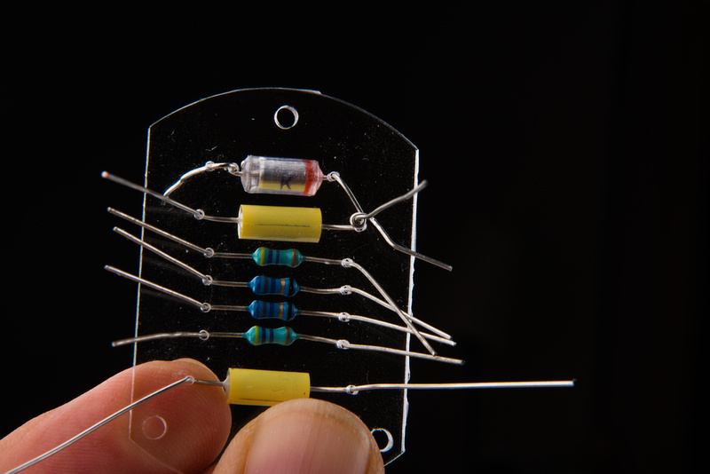
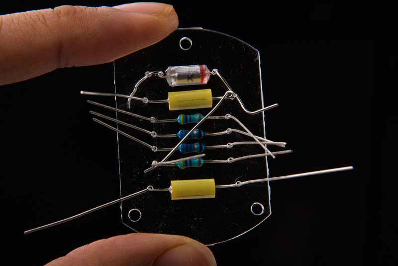
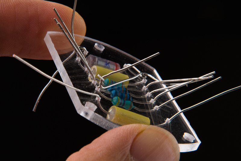
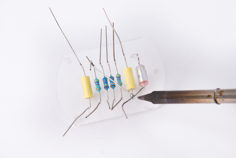
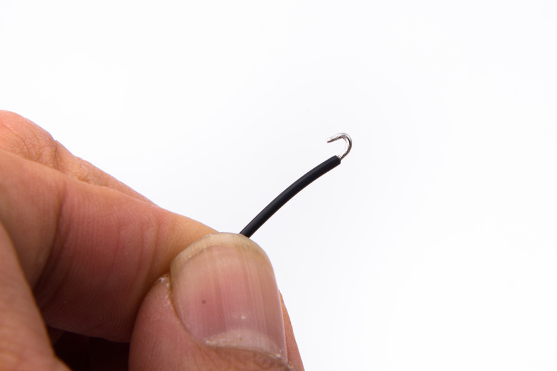
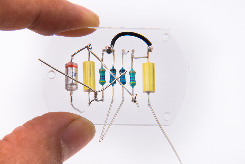
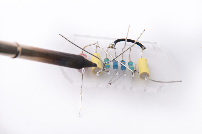
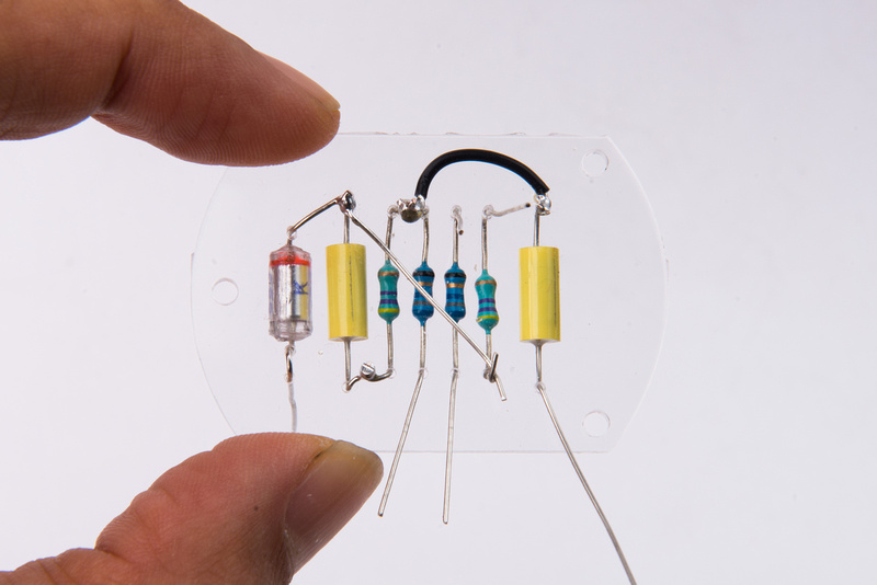
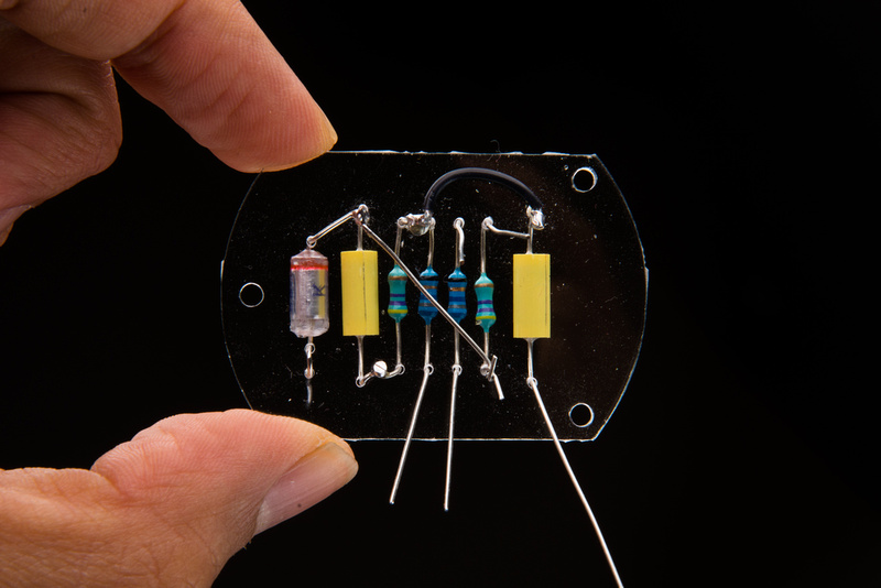
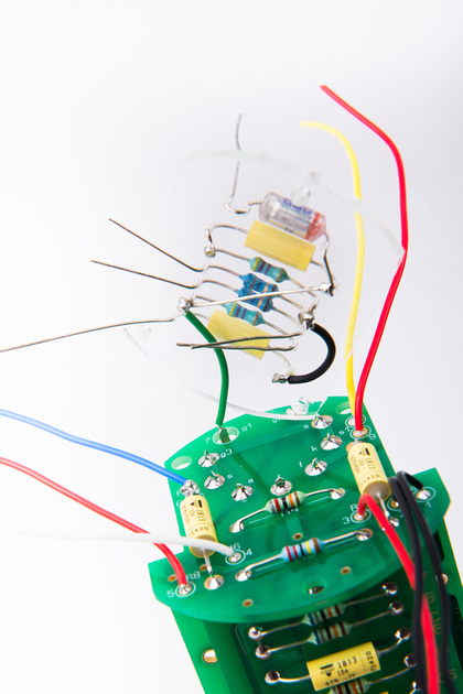
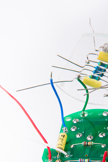
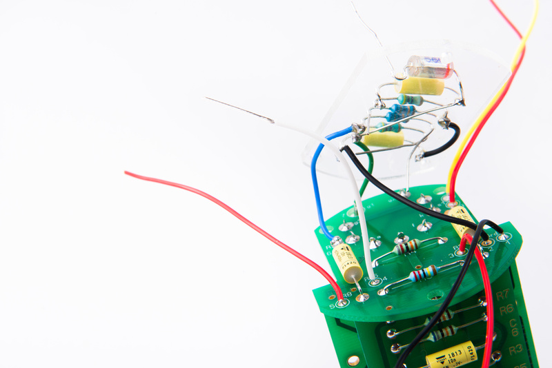
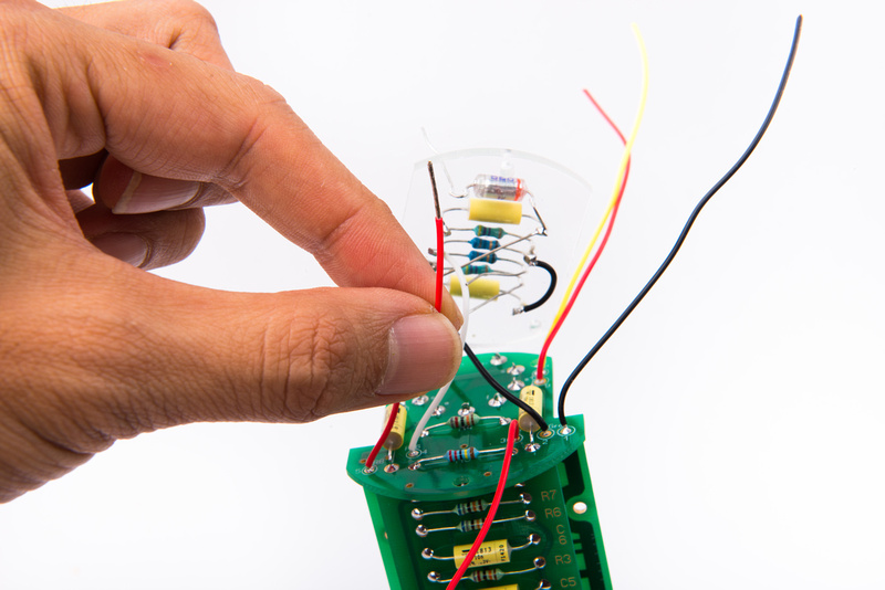
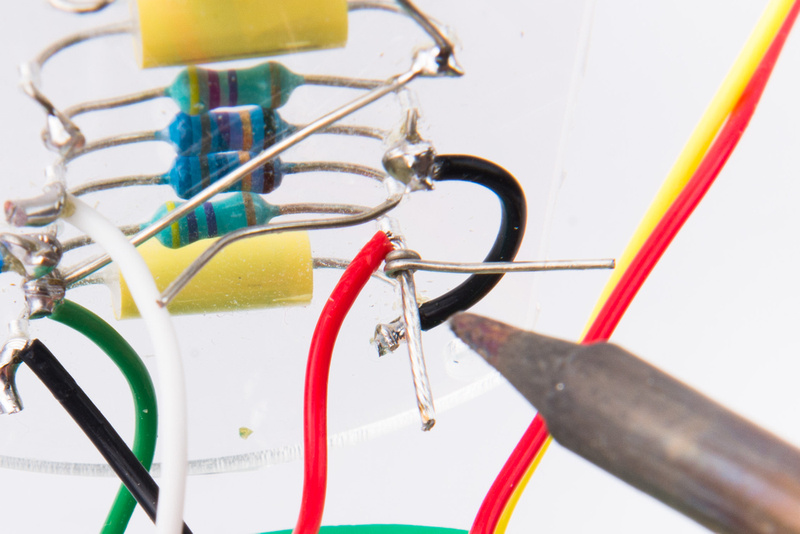
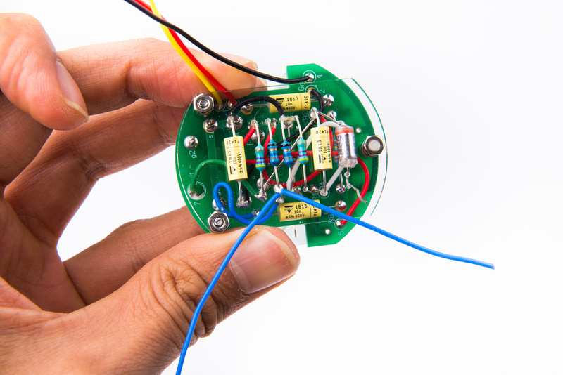
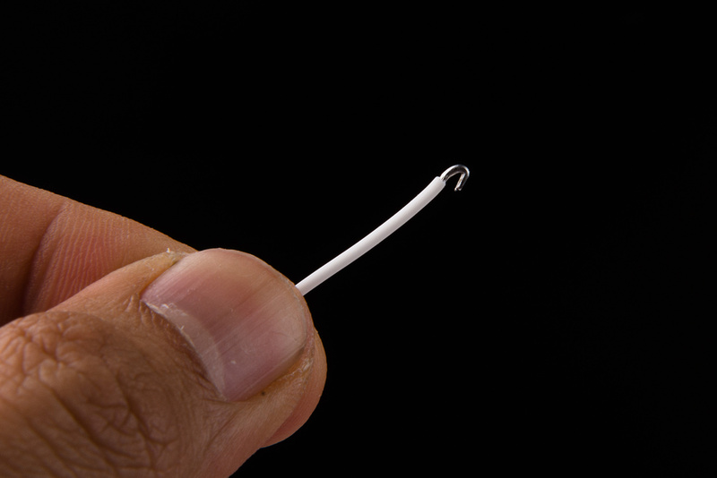
I realize at this point that I forgot to install a wire to the acrylic board, so I prep a white wire by stripping the end, tinning, and creating a hook.
This will attaches to C1.
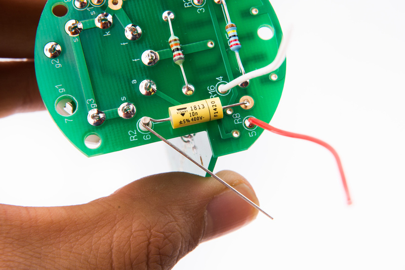
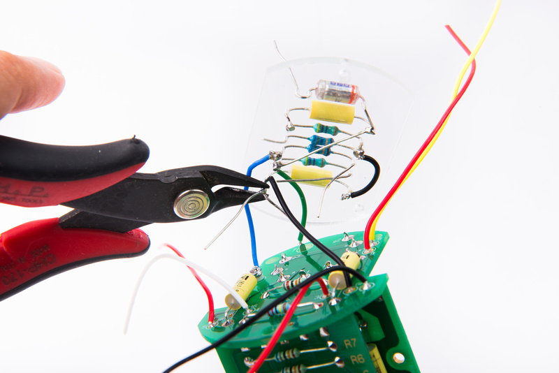
Next, trim and prepare the yellow wire coming off of the polystyrene capacitor C10.
This wire will connect to the floating center lug (E) on the S5 switch. Secure the wire with tape to the switch PCB to hold it in place while soldering.
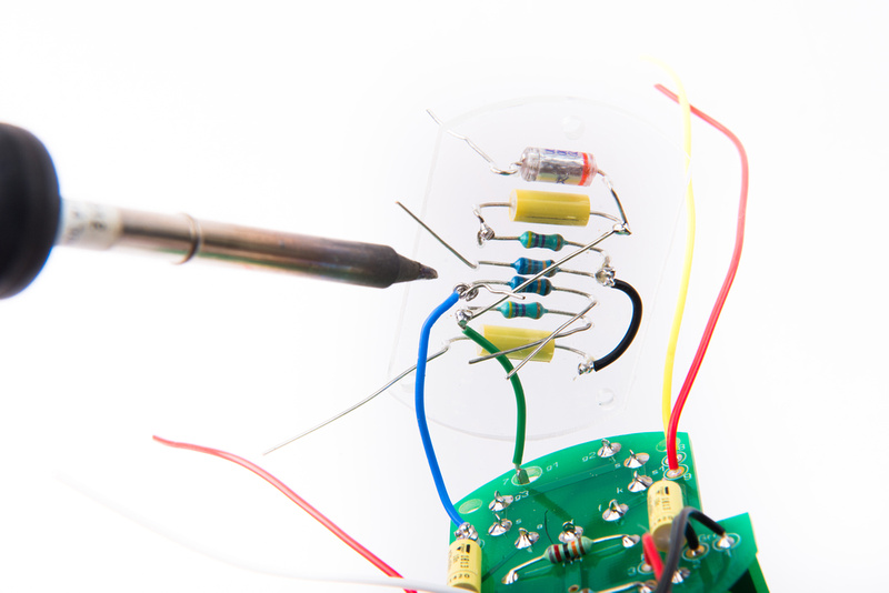
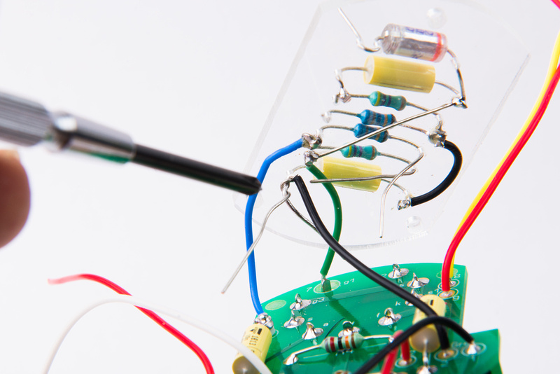
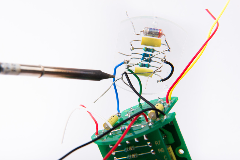
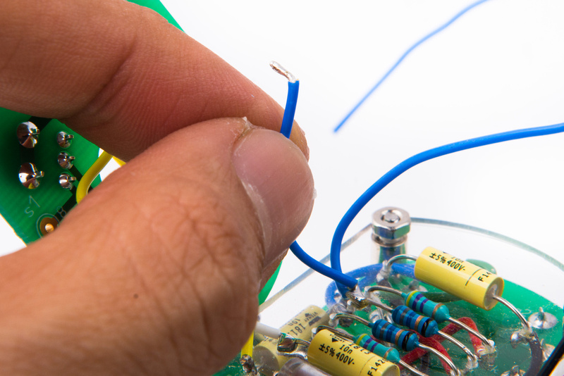
Next, trim and prepare one of the 2 blue wires coming off of R2.
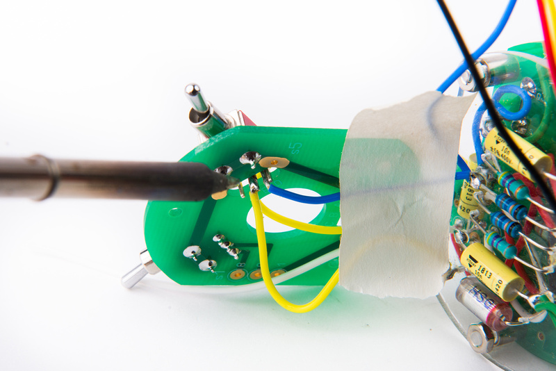
Solder this wire to lug "D" on the S5 switch.
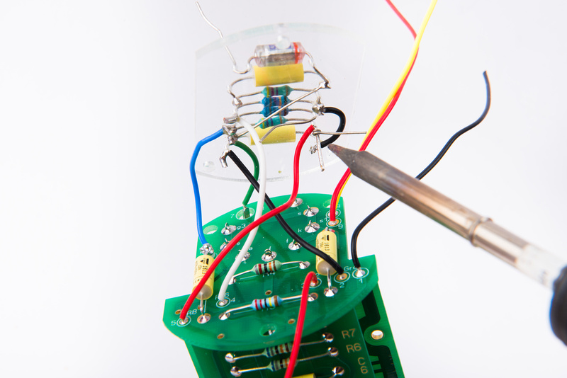
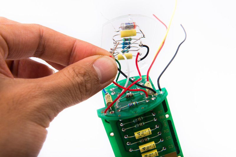
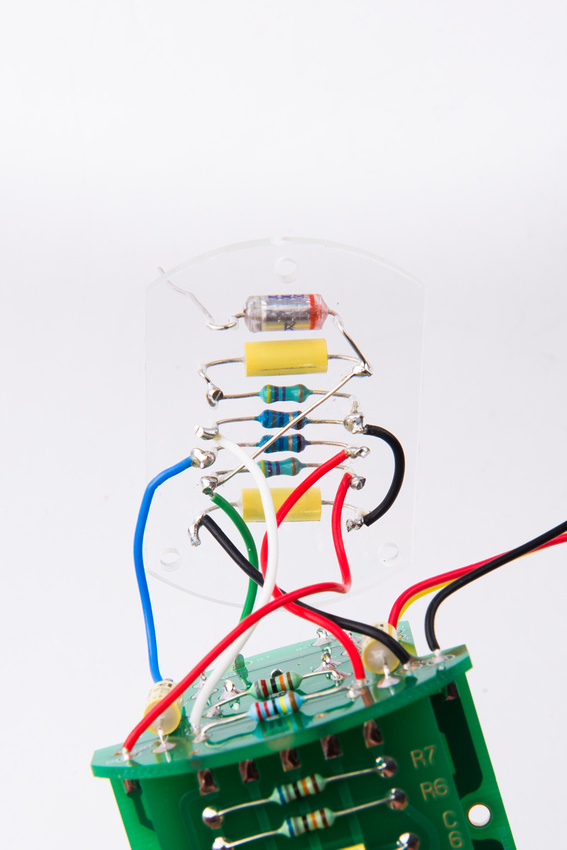
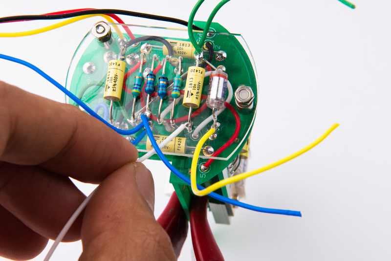
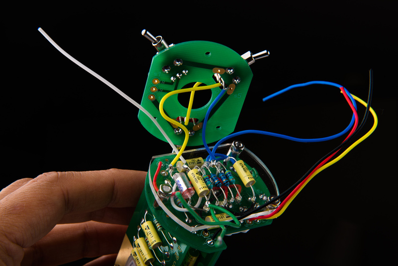
Here is how the wiring looks so far. . . next, prepare the white wiring coming off of C1.
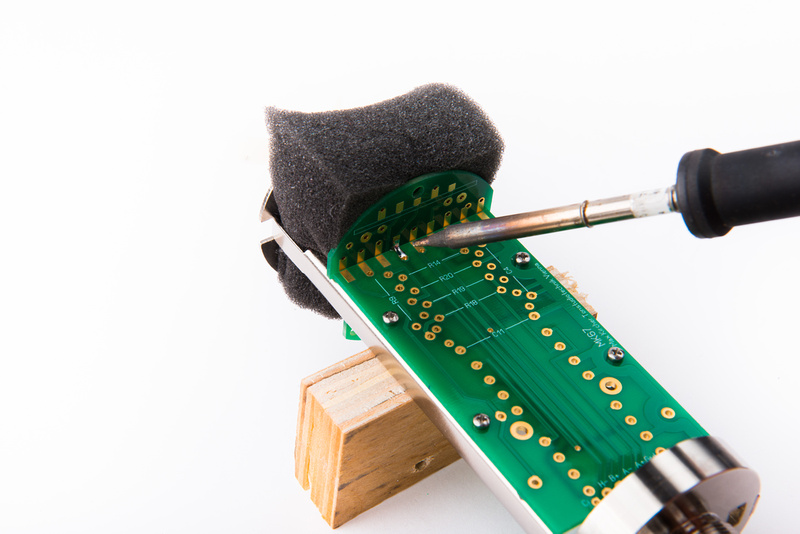
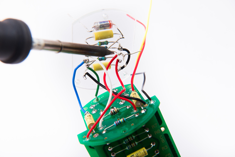
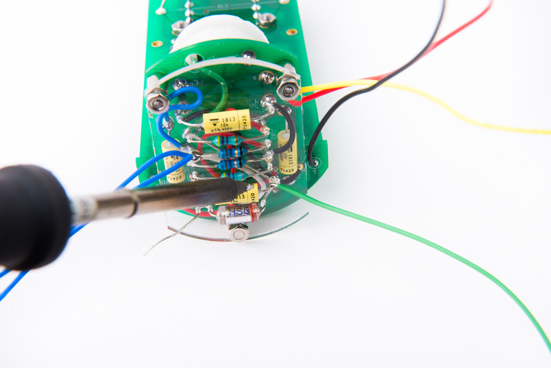
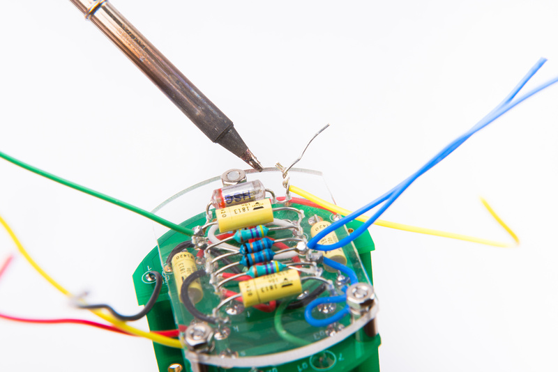
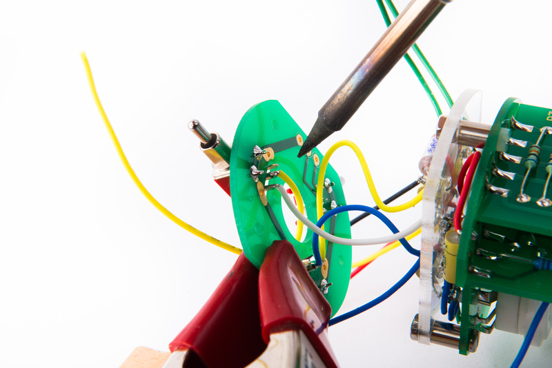
We will attache this to lug "A" on the pattern switch. At this point, I am using any available method to align the wires for soldering. In this case, I am using a spring clamp shimmed with a piece of wood underneath.
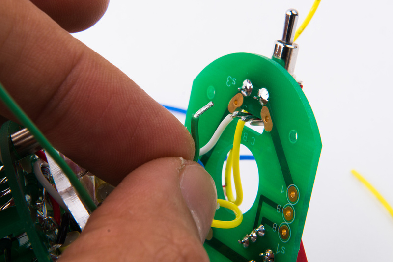
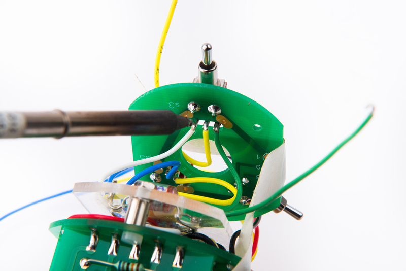
Next prep one of the green wires coming off of C1 on the acrylic board and solder to lug "C" on the pattern switch.
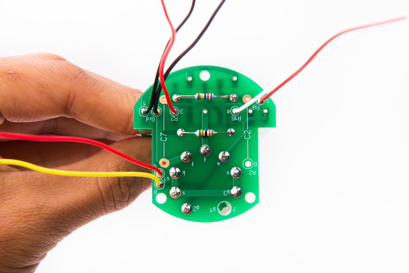
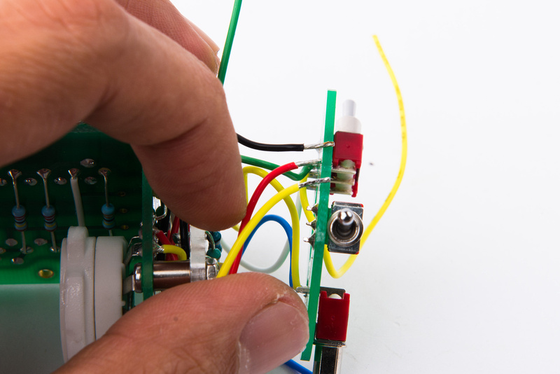
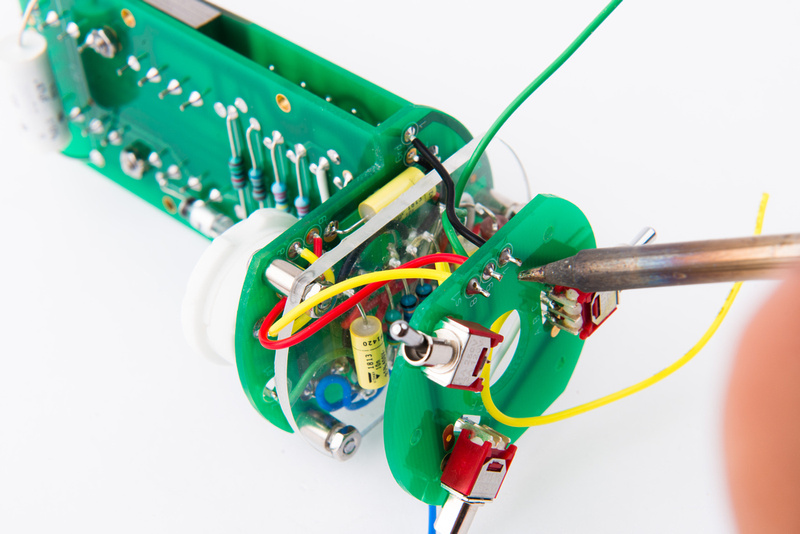
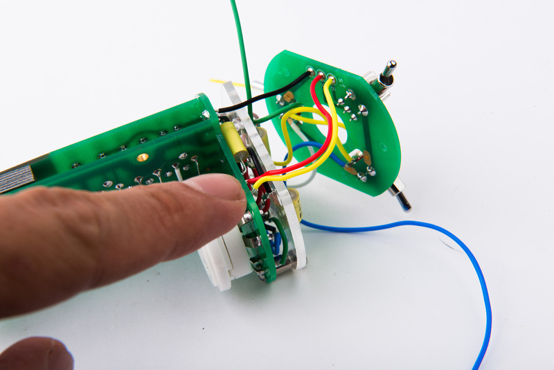
Next, locate 3 wires coming from the tube PCB. black (ground), yellow (8), and red (9). These wires connect to solder lugs 1, 9, and 8 on the S1 switch.
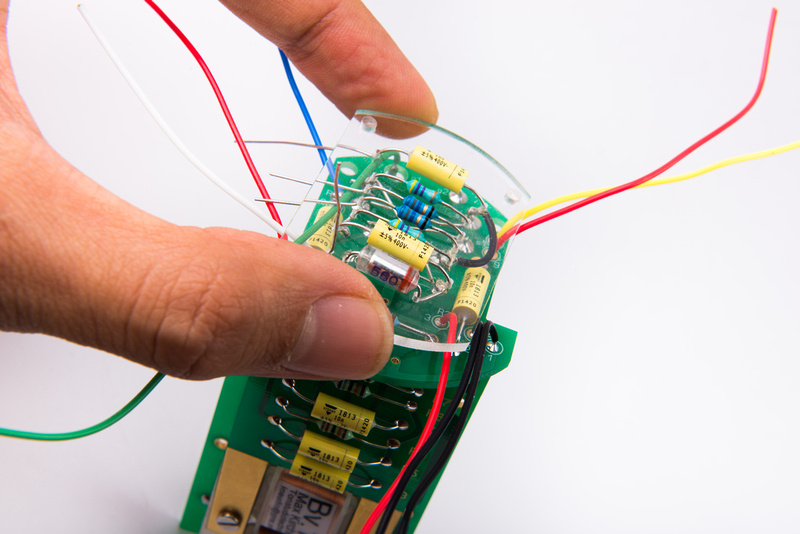
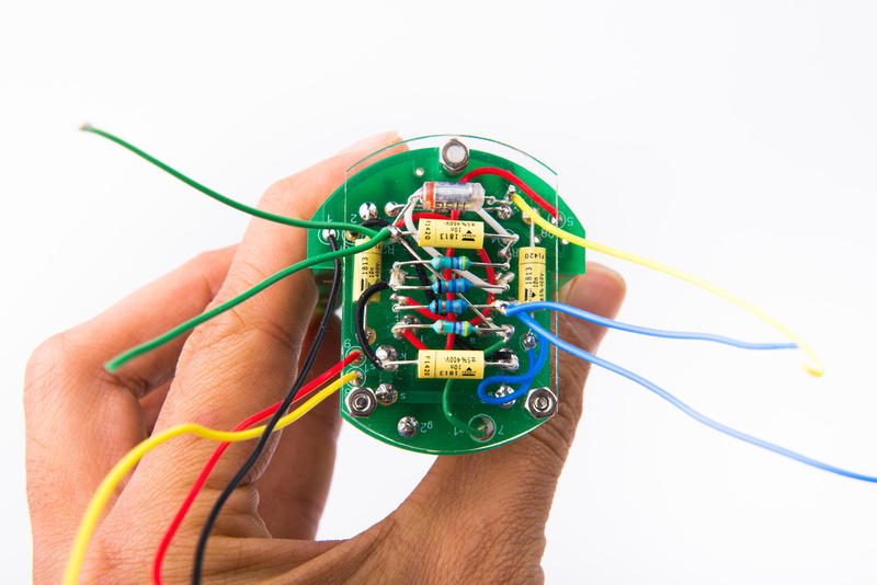
After installing the wires, I made a decision to route the wires on the "inside" of the PCB due to clearance concerns with the outside tube. This was easily accomplished by temporarily removing one of the standoffs securing the acrylic board.
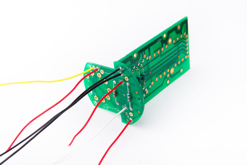
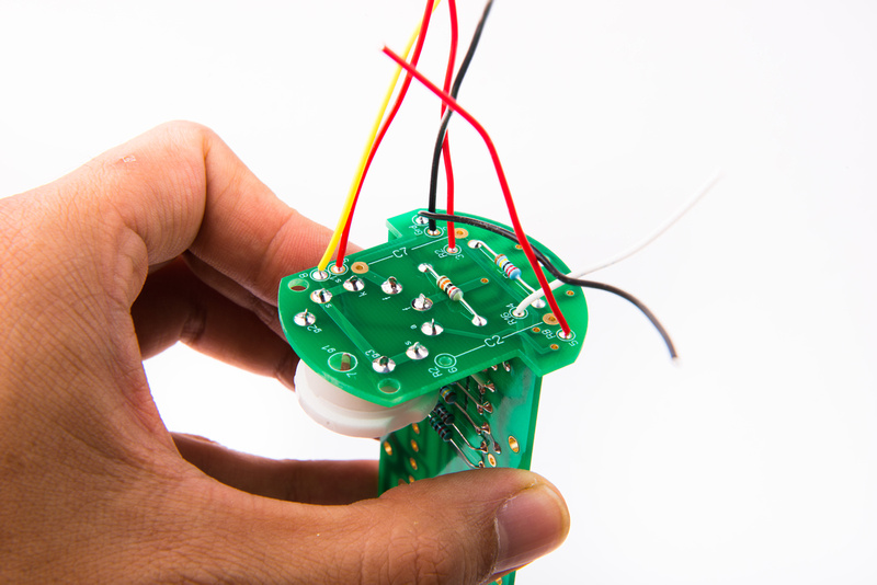
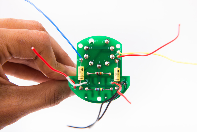
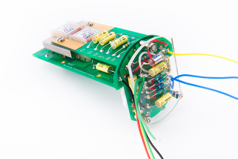
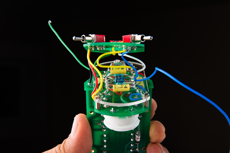
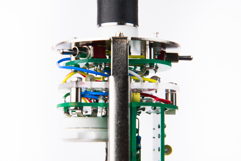
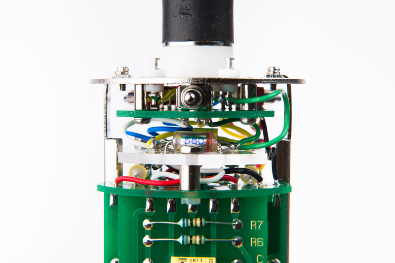
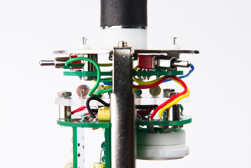
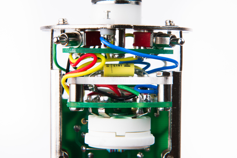
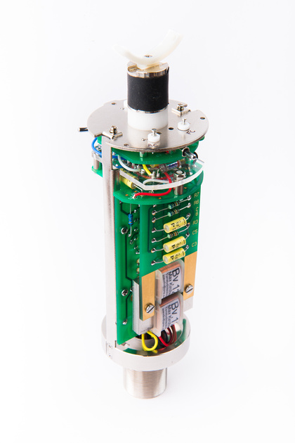
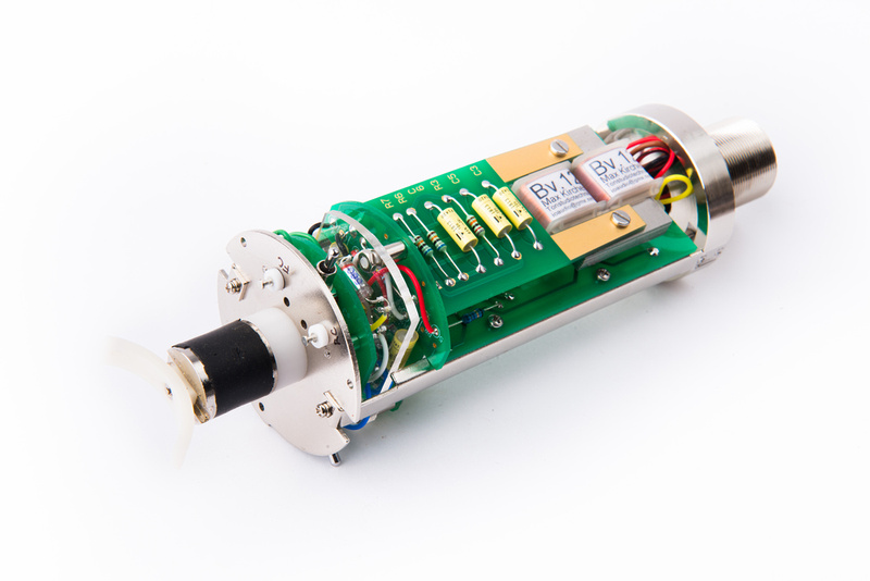
At this point, the switch PCB is completely wired in.
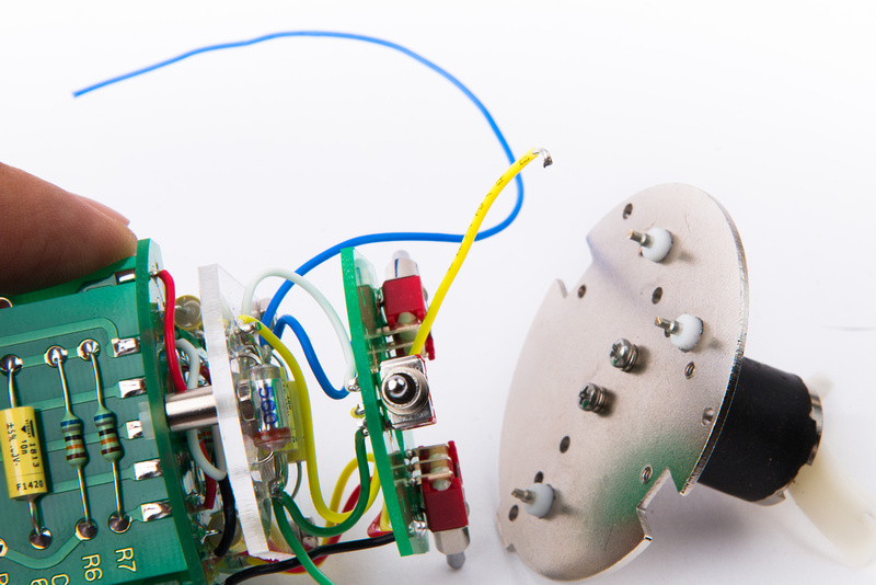
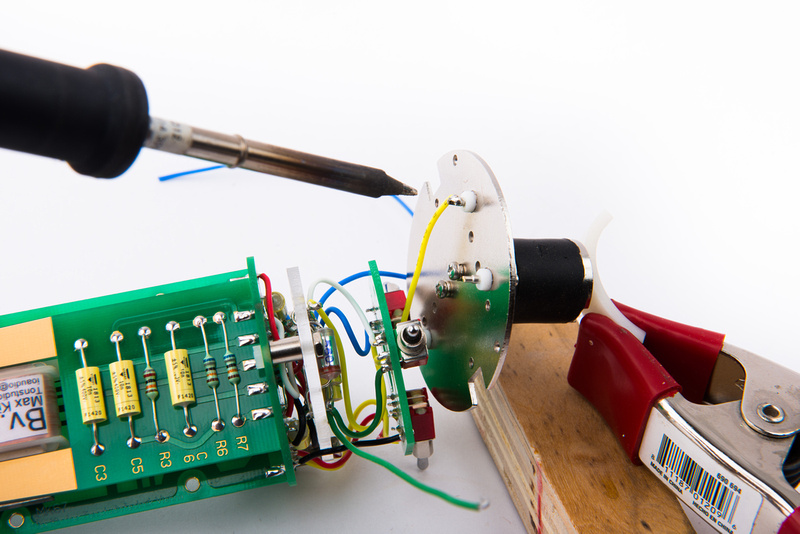
Remove the top plate of the microphone body and connect the yellow wire that is attached to the center of the pattern switch (lug B) to one of the teflon turrets. This wire will connect to the back capsule. We previously fed this wire up through the center hole of the switch PCB.
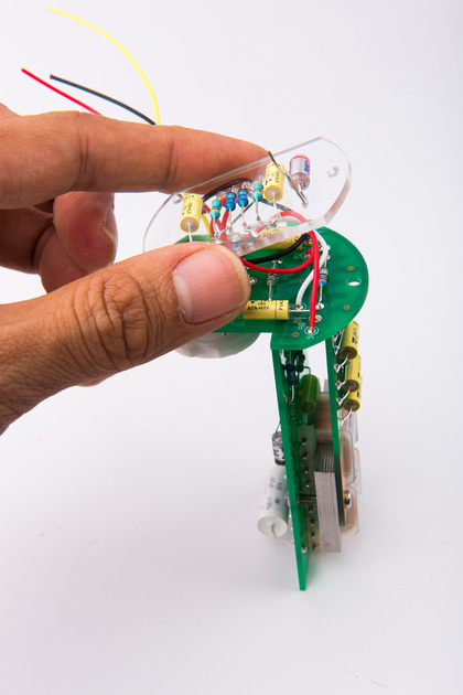
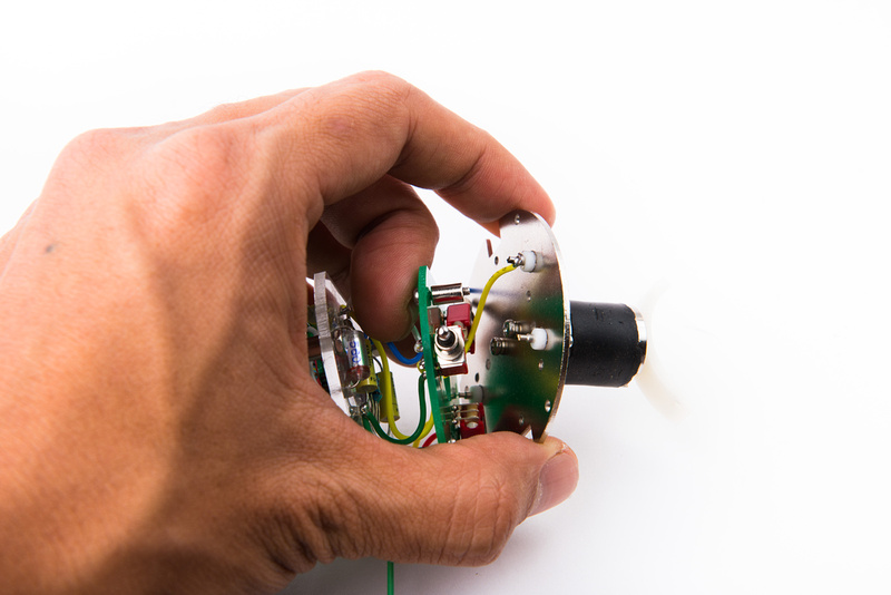
Next, install the switch PCB to the top plate with the screws and standoffs provided in the SYT-5 body kit.
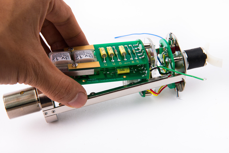
The top plate can then be re-connected to the frame rails and the PCB positioned inside the microphone body.
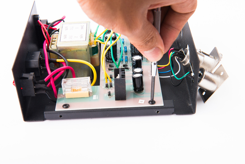
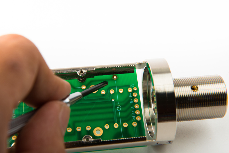
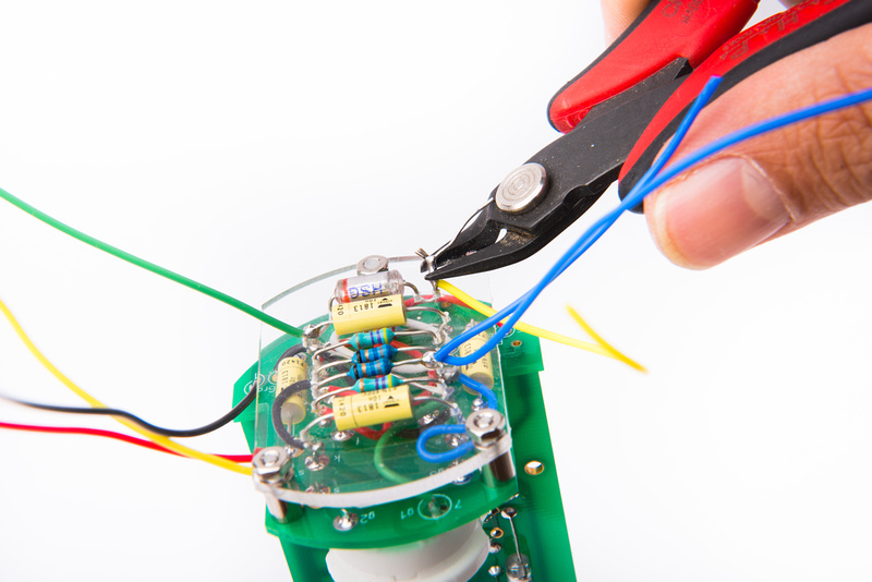
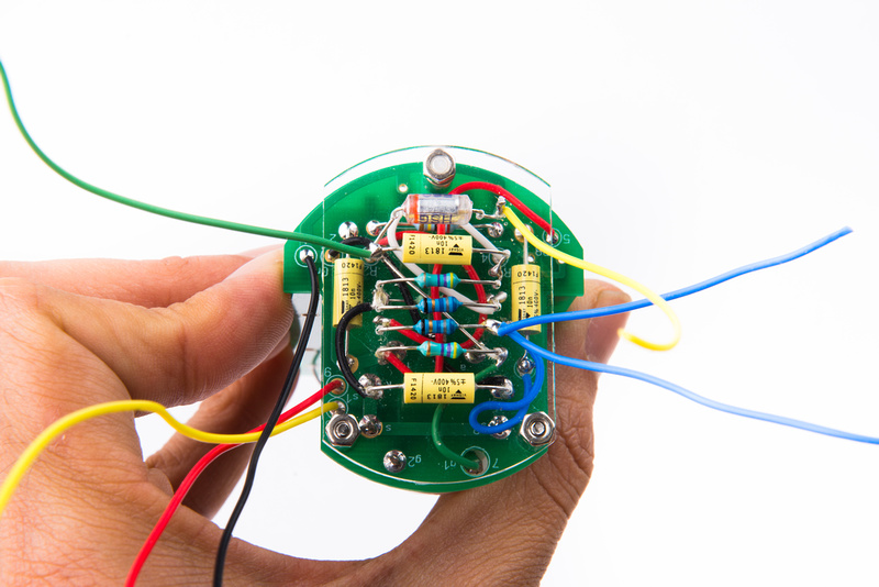
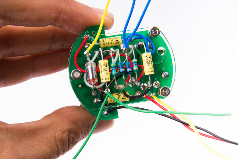
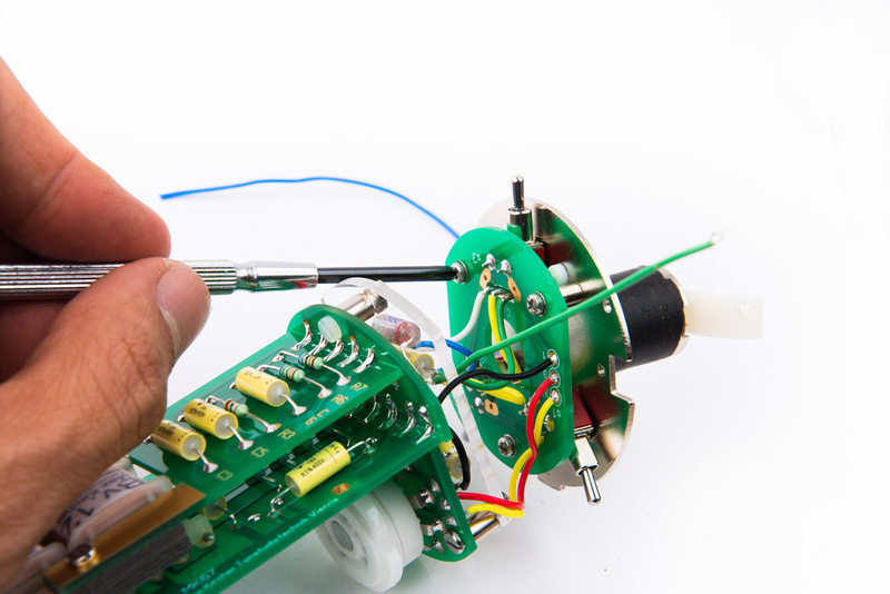
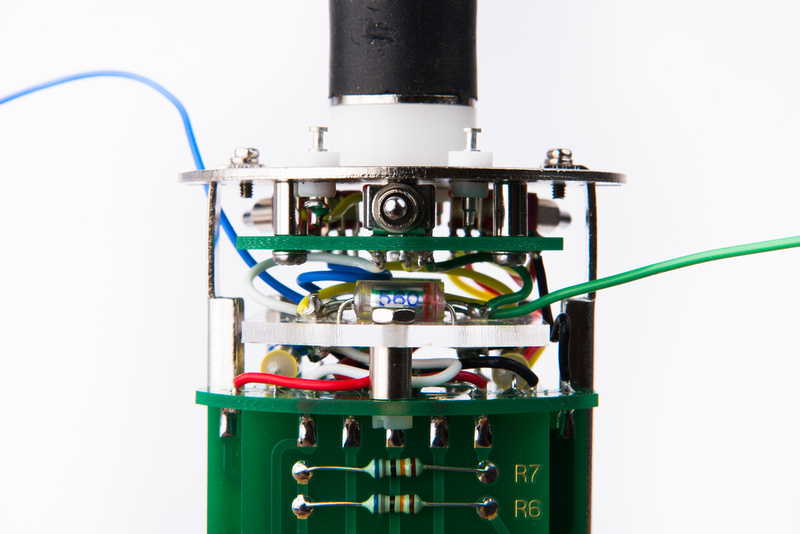
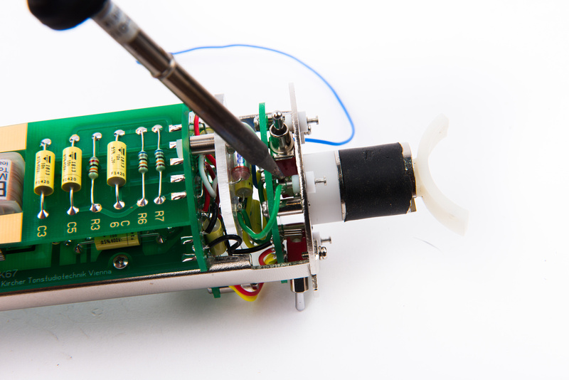
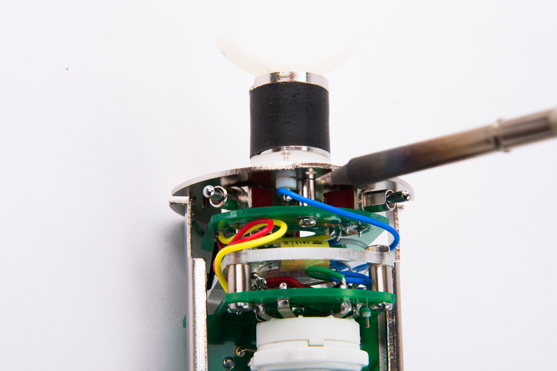
4 M2 screws attach the main PCB to the frame rails. As the boards are pressed into their final positions, adjust the switch PCB wires so that all of the ones coming from the acrylic board or connected to free-floating switch pins are free-floating and do not touch other wires. For this build, it was barely possible to accomplish this, and i had to do some poking and prodding with a small flat head screwdriver to move the wires into cooperation.
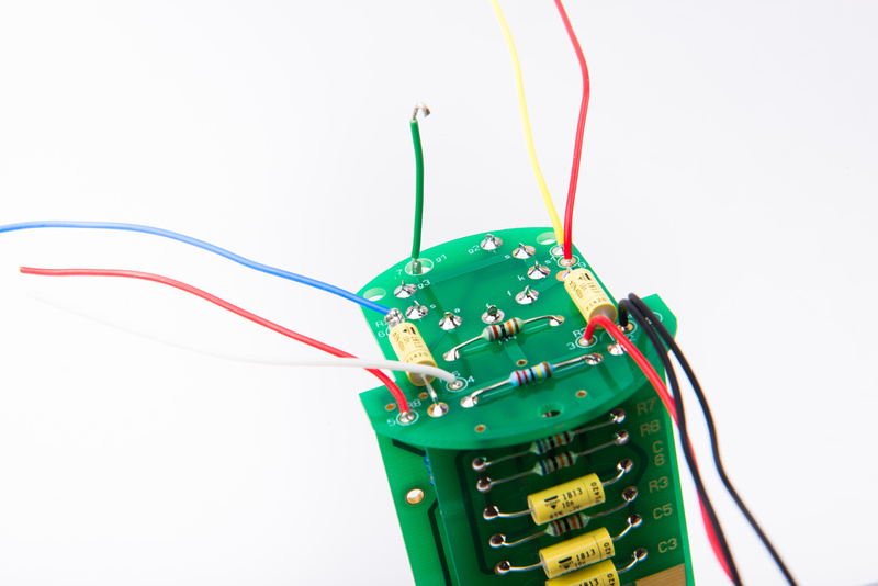
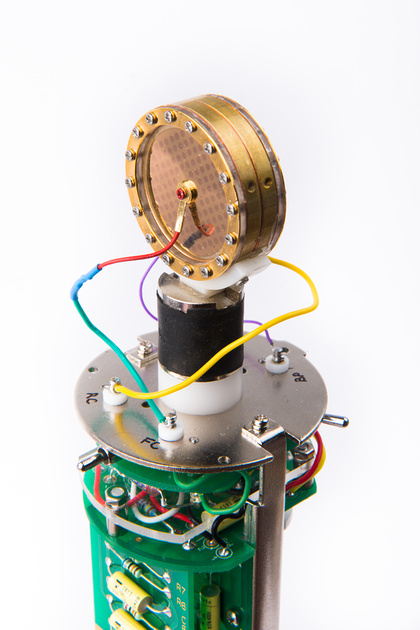
Two wires remain. The blue wire goes to the capsule backplate turret, and the green wire goes to the front capsule turret. These two wires should be routed to free float and not contact anything except for the turret teflon turrets.
At this point, the top portion of the microphone wiring is complete.
With the turrets labelled and the PCB secured, the assembly should remain largely undisturbed for some time assuming we do not have any mistakes or failed components inside

One more test fitting confirms that the switches are still aligned with the outer tube slots.
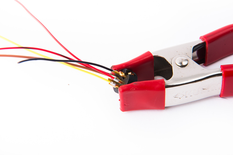
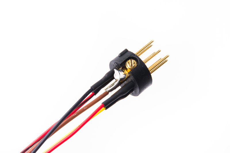
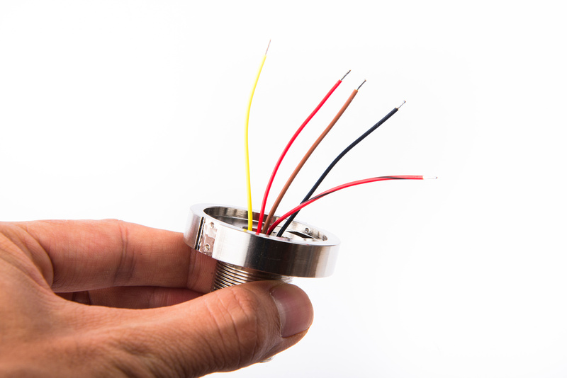
Next, install wires on the 7 pin XLR insert. To match with our power supply:
pin 1 = B+
pin 2 = heater
pin 5 = audio +
pin 6 = audio -
pin 7 = ground
Pin 7 (ground) is bridged to the chassis tab at the connector.
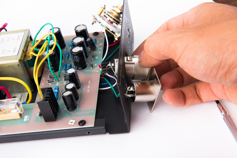
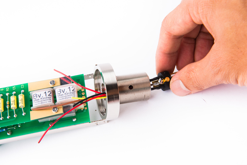
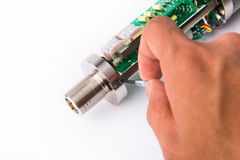
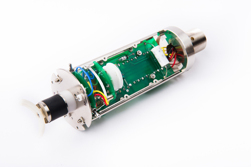
Remove the 4 M1.6 screws securing the bottom piece of the microphone frame and install the 7 pin XLR insert.
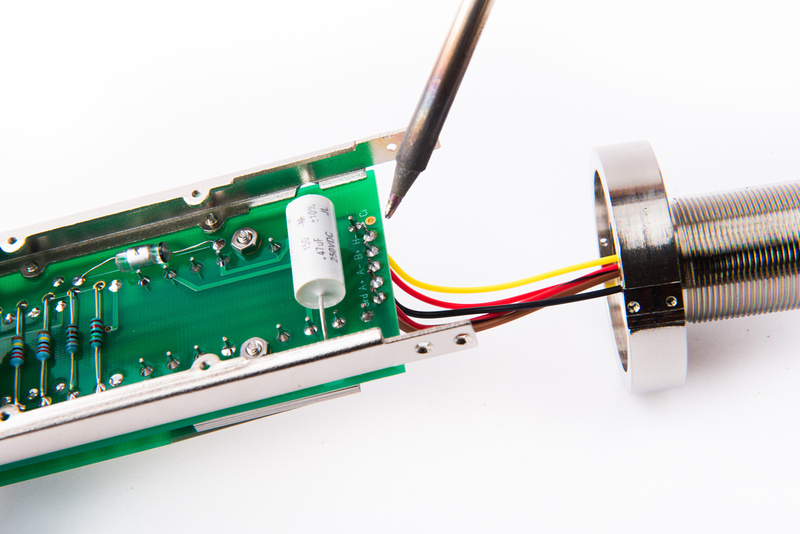
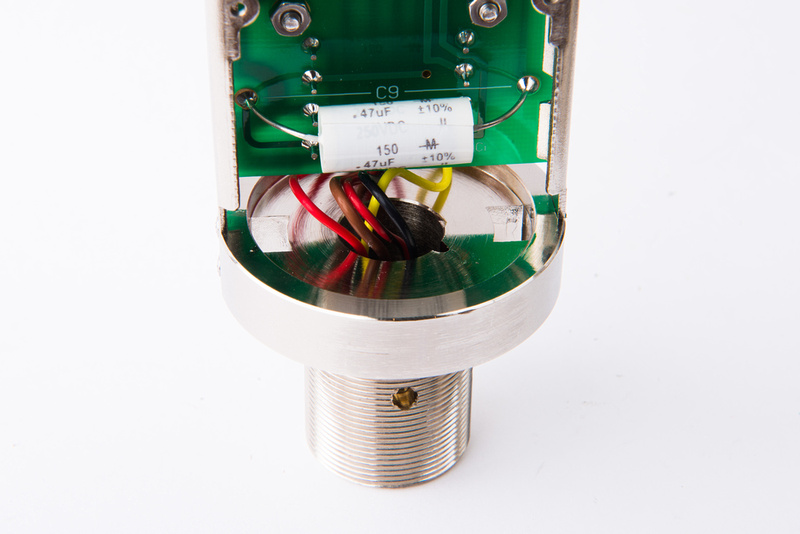
Leave enough wire lead to back the XLR insert out if repairs or changes are needed. I estimate it is possible to neatly leave 1/2 to 1 inch of wire than I have in the photo below and still route the wires very neatly.
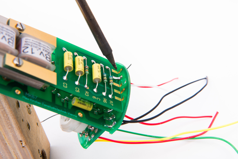
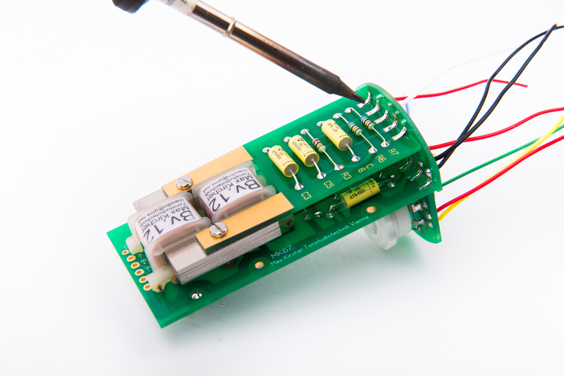
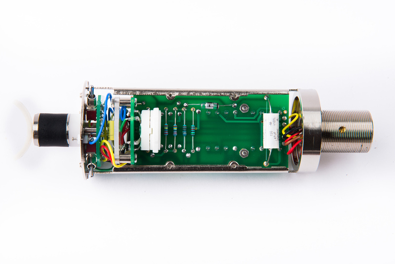
Solder the wires to their designated lugs at the bottom of the microphone PCB.
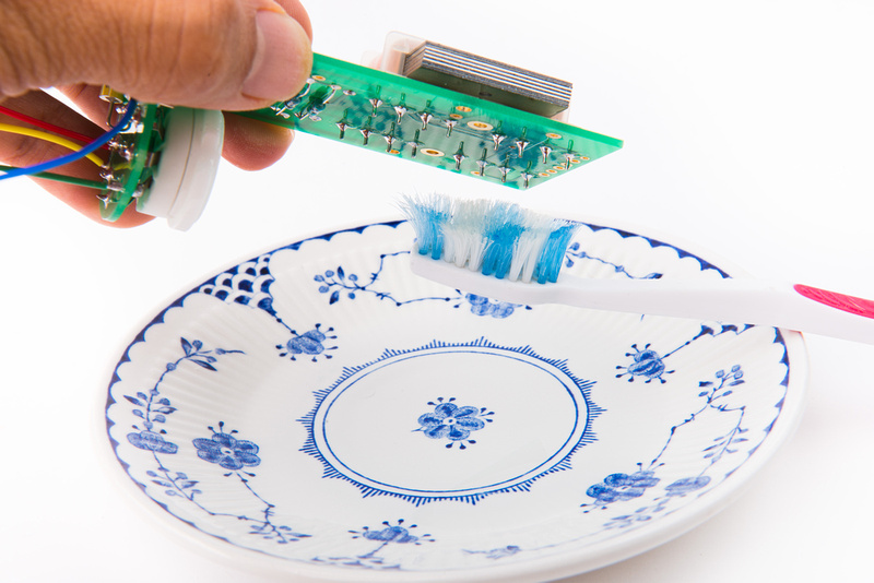
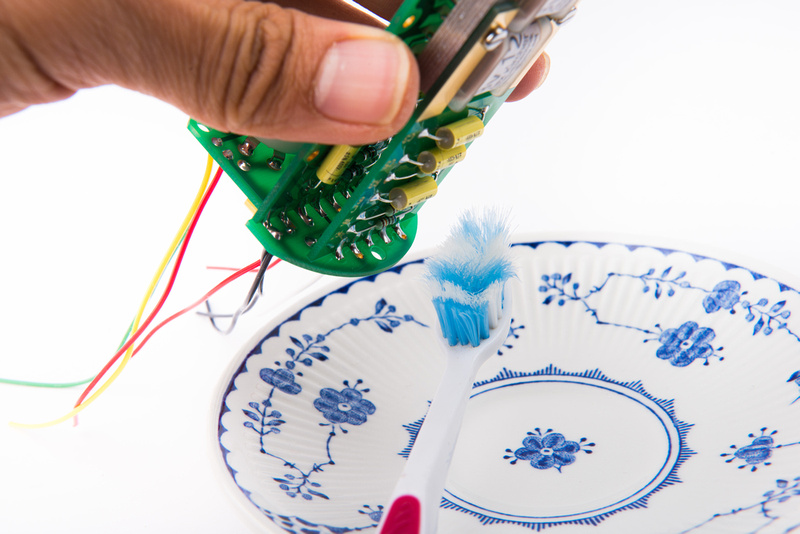
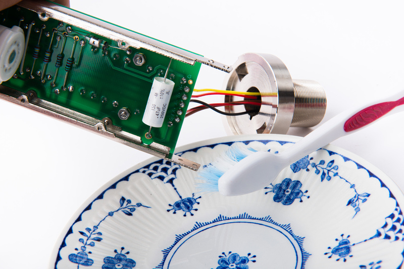
Clean the solder lugs with isopropyl alcohol being careful to avoid the capacitor and transformer.
Neatly route the wires and re-install the base piece.
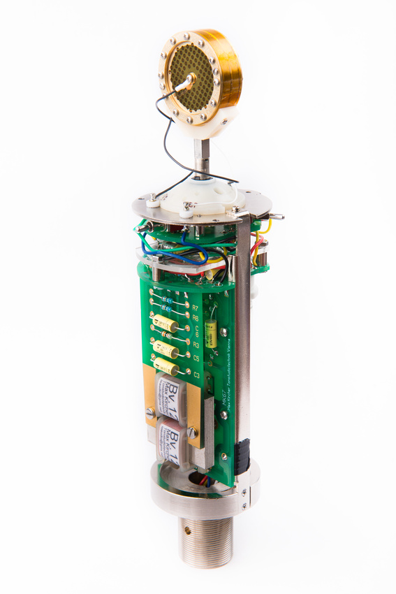
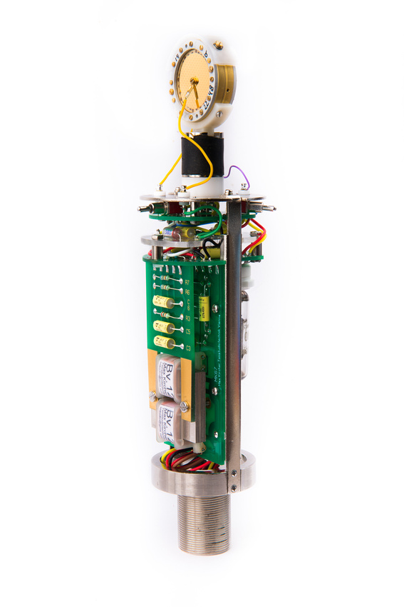
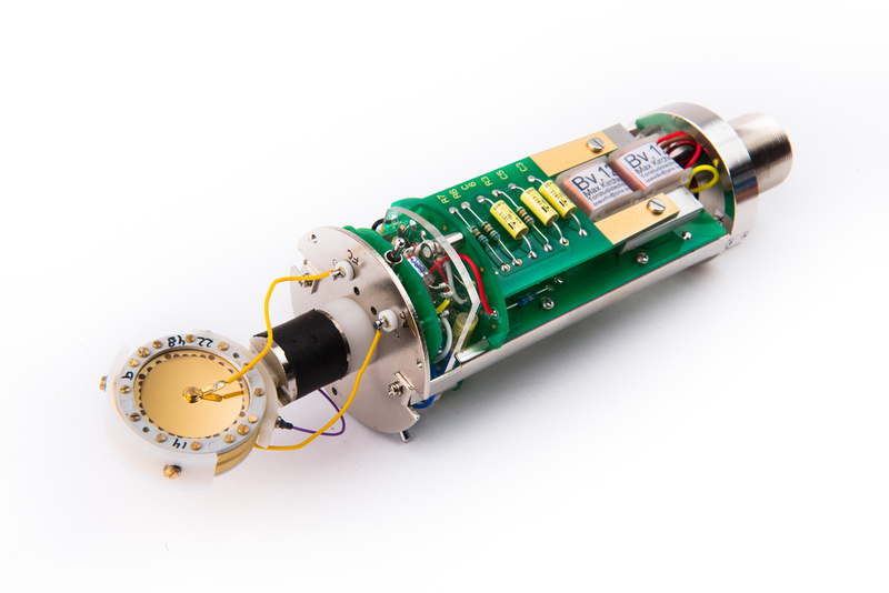
At this point, the microphone is completely wired up and ready for a tube and capsule.
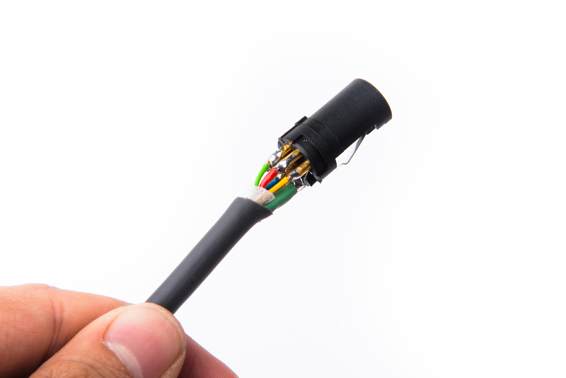
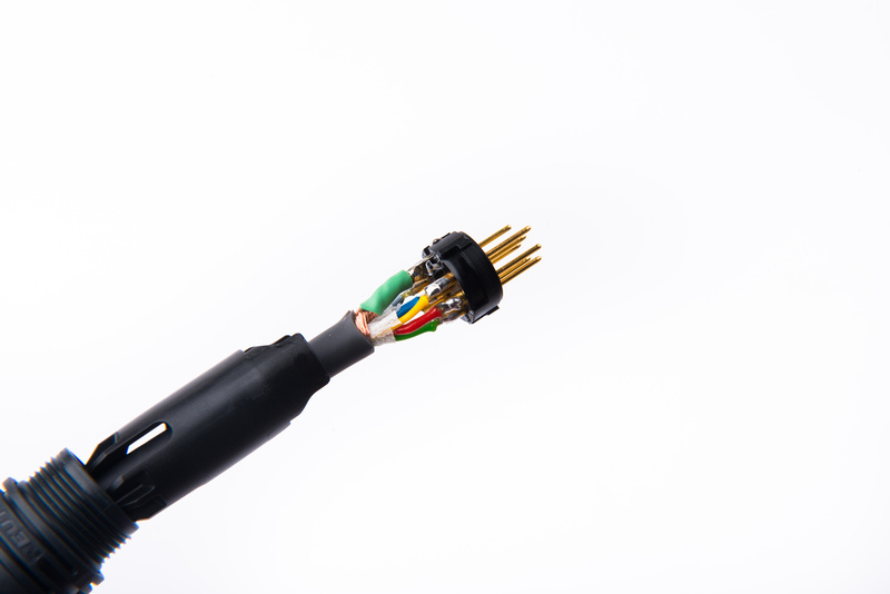
Next, I make my 7 pin XLR cable. I am using Gotham GAC7 cable which contains 2 large gauge conductors. I use these on pin 7 and pin 2 of the cable as these are my heater and ground. For this cable, I do not connect the shield to the ground pin so all of the conductors are straight through on the cable. The grounding scheme can be determined at the PSU or in the mic body.
The solder lugs are close and there are a lot of wires. Carefully verify with a multimeter that there are no shorts in the cable.
Next, for function testing, install a known-working capsule that you are not afraid to destroy. This happens to be a capsule from a stock Alctron MK47 microphone.
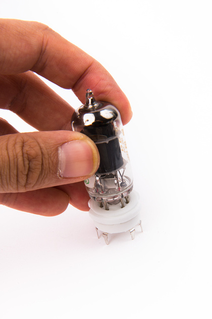
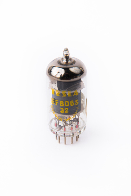
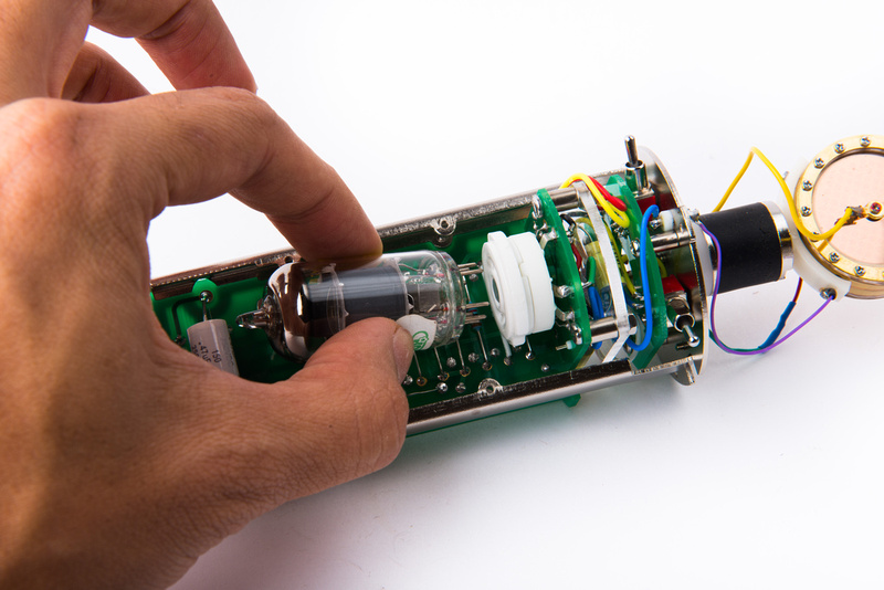
Also, install an EF86 equivalent tube that you are not afraid to destroy.
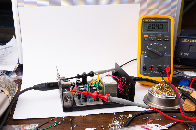
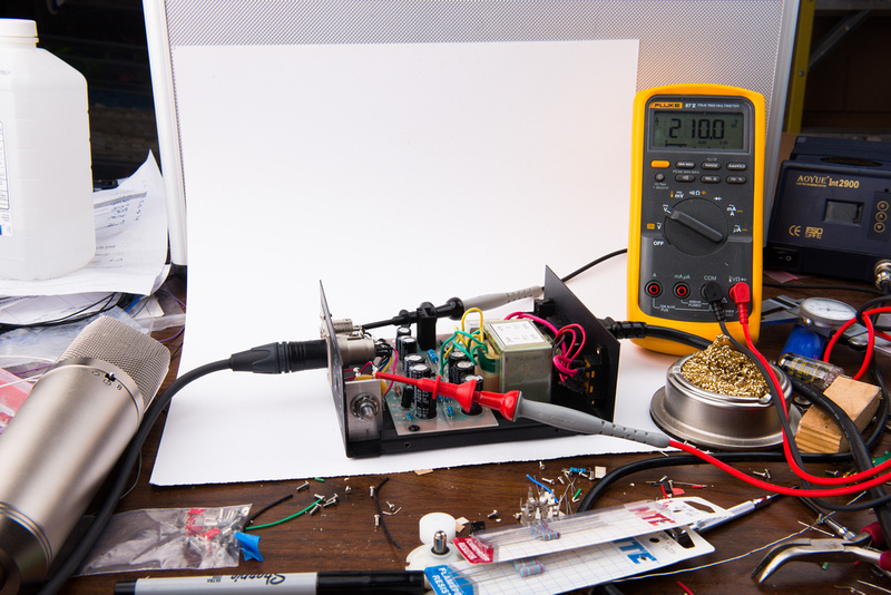
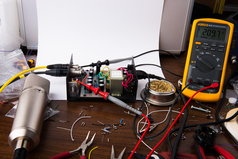
Double check that all connections are as they should be, and fire up the microphone! If all goes well, there should be no smoke and everything should work correctly. This build functioned flawlessly right away. It is raining in Northern California tonight, so I have wider line voltage fluctuations than normal. The passive B+ supply will fluctuate with the line voltage. This is normal.
With the microphone confirmed working, it is now time to replace the function test components with high quality pieces for the final build.
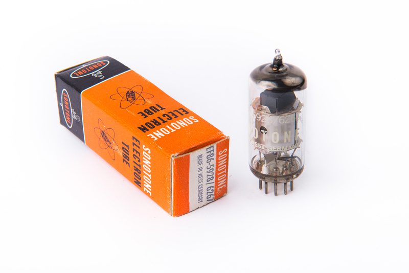
I am using a Telefunken manufactured EF86 tube that is branded for Sonotone. For this mic, I simply emailed Christian Whitmore and requested the best type EF86 he had on his current shelf, and he asked if I was concerned about the branding. I was not and only care that the tube is original factory spec and a good sample so he sent the Sonotone.
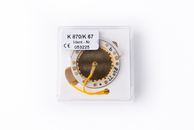
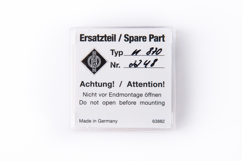
As a baseline reference in this build, I will be using a new production Neumann K870 capsule. These are available directly from Sennheiser.
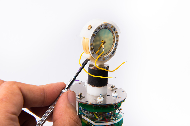
The saddle that came with the donor body had holes that were just slightly too widely spaced for the original Neumann capsule, so I used a small drill bit to lengthen the screw hole slots on both sides towards center.
Use M1.6 screws which are not included with the capsule to secure the capsule.
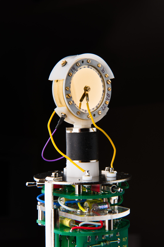
A backplate connection tab is also not included with the capsule, so I stole one from another cheap Chinese capsule in my drawer and attached a purple 28 gauge stranded silver teflon wire to one of the screws connecting the capsule to the saddle.
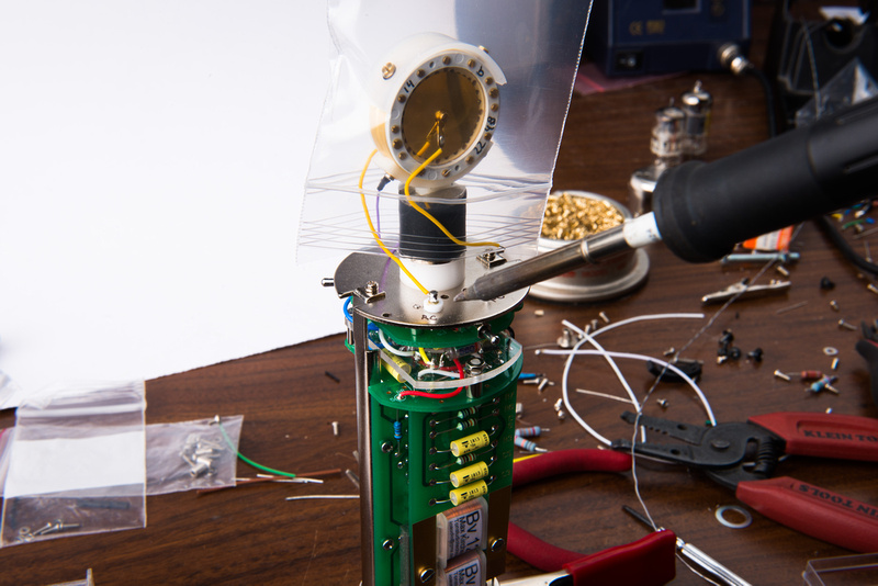
It is critically important to keep splashing solder flux and hot vapors off of the capsule when soldering. Protect the installed capsule with a plastic bag when soldering near it.
The leads on the capsule only extend far enough to reach the teflon turrets, so if you plan to use an original capsule, I recommend installing these.
With the final tube and capsule installed, the microphone is complete. We will need to re-trim the B+ voltage with the new components and then we should be able to put the microphone into service!



























![Electronics Soldering Iron Kit, [Upgraded] Soldering Iron 110V 90W LCD Digital Portable Soldering Kit 180-480℃(356-896℉), Welding Tool with ON/OFF Switch, Auto-sleep, Thermostatic Design](https://m.media-amazon.com/images/I/41gRDnlyfJS._SL500_.jpg)


