Orange 86 Build Thread - no PCBs for sale

GroupDIY Audio Forum

Help Support GroupDIY Audio Forum:

This site may earn a commission from merchant affiliate links, including eBay, Amazon, and others.
Thanks Alex. I totally agree on all points. I just raided my storage and found a steel LA2A 3U case that will fit one unit comfortably (although having the tubes horizontal seems sketchy but doable) and I can easily load the Ecor off the back like an LA2A...going to order some different tubes just using what I had around...

The white noise is just my freakish ears...all of my equipment has it to some degree (even with good power conditioning) and my desire for absolute silence has always been unreasonable...some of it is from the listening channel I am using.

Need to scope everything out but have just been building in the house (moved my shop 6 months ago and everything is in storage).

Charley did a lot in this pcb...I agree with the DI and phase stuff, a little overkill in some of it, but I am glad I did it now, it was problematic in the building though.

I think a simpler design, AC heaters and you could hang the edcor off the back of a chassis...you might lose phantom, phase and the DI but there are ways of doing some of that without all the relays...simple switches etc...

I will say this is the first preamp in my arsenal that I love going direct in with electric guitar...up until now I re-amped and stuck a mic in front of a speaker...but this...man it sounds good...I can hear the fender influence in Charleys build...

The gain staging is a little unusual in what it sounds like...I've checked my switch and it is stepped correctly, but when I use it there is a point where the volume doesn't go up so much but the sound changes in color...I love that feature...gonna try the squish thing next.
 
Sounds good :)

I also used the 6n1p in the output - had slightly higher gain and  I felt I preferred it over the au7 I had there.
(and 6922 also). Seemed somewhat more .. heroic :)

Mine has edcor psu and output traffo - pretty happy with it. A little 'grainy' but I  find but that can work well to give character. Noise at unity was very low for me - some 4dB above soundcard 'loopback' noise floor.
Frequency response was very flat even approaching 40KHz at the high end and dropping a maybe 2 dB at 20Hz.
I have Haufe line input traffo and a UTC mic traffo - I added a relay switcher there.

I use mine mostly for bass/gtr and I agree with you - it's probably my best for that purpose.
I too hear a definite fender thing there.

I'll check what you say regarding some change in sound depending on the attenuator setting. I'm putting last touches on mine now. I do see some pretty marked increases in distortion products at the lowest attenuation settings - as you would expect by reducing negative feedback in a simple class a implementation.

My next ones will use some cheaper UTC output and some Carnhill output. And I'll be messing with the squish thing some too.

I did use dc heater but generally prefer not too - unless there is a good reason, like in a vari-gm limiter or so.

Be great to see this in MkII with a relay switched line input and onboard phase reverse added.


But hell yeah - what a great sounding pre and simple, cost effective to boot!
 
hey guys

I'm a little more than half way done with populating my board.

What is the blue board that I have seen paired up with many of these? I'm assuming it has something to do with powering the relays and +48V. I need one!! Is it still available? the board was given to me as a gift but it did not come with the blue PCB. I can't find what C1 is supposed to be. C1 comes from the squish pad and the other end connects to V1. Can both relays in this project be the same relay? I assume yes.

What are the cons of using the bridge rectifier setup with two diodes compared to the weatstone style?? I'm a little rusty about that since the lesson was a few years ago.

Thanks regardless.
 
buildafriend,
you don't need the psu board that charlie made.  it was additional and i didn't purchase it either because i was just going to perf board the phantom and relay voltage supplies and use twisted AC pair for heaters, but if you are not inclined to do so mnats has a nice little pcb you could purchase http://mnats.net/board_sales.html which will supply you with relay power and phantom.

as for C1 have you read the docs on the first page of this thread?  C1 is clearly listed on the schematic.  please go over the schematics and familiarize yourself with the circuit before attempting to build the Orange 86 and PLEASE FOLLOW SAFE PRACTICES WHEN WORKING WITH HIGH VOLTAGE!

both RL1 (DI) & 2 (POL) are the same type i believe, please look at the schematics and BOM for reference.  i can't remember the pcb, but look at the footprint and BOM for type (12V, but could be a 24V relay voltage i guess depending if using mnats board - less heat wasted at v-reg).

hope this helps.
best,
grant
 
Anyone using two different power tranx is for the 48/relay/DI, Charleys board also gave the option of running DC as the tube voltage rather than raw AC, which some prefer.

I think my C1 was an orange drop rather than a WIMA, so cannot comment on WIMA footprints...

I went DC since I had Charleys psu board and just used everything in the BOM for it...

By far the best preamp I have although with the Edcor PSU driving the tubes its a bit of a noise issue to tame hum...

Probably one of the nicest projects around here with the variables available, Charley did a bang up job on it.

Good luck with your build.
 
PM me if you can't find the docs you wants.

This is too nice a build to miss out on!

Cheers
 
Found some docs - here's one for the orange86 assembly ...
 

Attachments

  • Directions.pdf
    939.9 KB · Views: 75
And populate any tall components at  back of the pcb so you can put the front with the lorlin and mount it up against the face plate.


Here's the pad-BOM. Looks to be -15 and -20 db.
My excel doc (v1.4) has multiple sheets, PAD PCB is the 4th one.
 

Attachments

  • PadBOM1.4.png
    PadBOM1.4.png
    11.8 KB · Views: 28
The lorlin (alpha) is the 4pole, 3 way switch - theres's only 1 kind. As long as it has the 4 center pins, it is it.
 
Thanks re the sig - an old saying I had when I worked in the field.

Actually I always seem to order a few wrong parts too - especially from mouser. Dunno why, but that resistor I painstakingly checked turns out to be a teeny tiny one instead!  Oh well, such is life.

Unfortunately I only have the bom you do, so can't halp much there. On the bright side, there cant be too many types out there.
 
Much apologies buildafriend.  The o/p XLR is a Horizontal Neutrik D series PCB wit 4mm spacing for the pins and 4.7mm for GND

http://www.neutrik.com/en/xlr/xlr-chassis-connectors/d-series/

Mouser:
568-NC3MDH-B
-other colors are fine obviously

Please message me if you are still having trouble with the missed details.  I will give u my email or get your phone number and help.
BTW, you may not want the power transformer that close to signal transformers.  You may want to go with the a layout closer to what I recommended. Though it's hard to make out your layout.

It seems 90% of people who built this have been secretively doing so. Hence, I haven't gotten much feedback on edits needed for the build docs.  I must apologize for the lack of build docs actually.  So message me for them too. 

All I can say is life happens, and I haven't been here much. But I will try to check in here more.

I do hope the ones who have manage to complete this are spending less time here and making beautiful reproductions and disseminating wonderful sounds to all corners of the universe.

-Peace and Great Potential to all!
 
alexc said:
Sounds good :)

I'll check what you say regarding some change in sound depending on the attenuator setting. I'm putting last touches on mine now. I do see some pretty marked increases in distortion products at the lowest attenuation settings - as you would expect by reducing negative feedback in a simple class a implementation.

Agreed about Ac heaters.... NFB THD I found to be pretty clinical on my AP.  I did those low settings for NFB for DI friendliness. So when recording drums or other hot signals I would use the pad and keep the gain as high as possible.  Semantics? u are talking about the NFB-Gain, right?

thanks for supporting the new builders fellow DIY-ers
 
Good to see you back Charlie :)

Thanks again for this fab implementation of the classic - the Orange86 sounds to me like a tube pre should.

Mine are very satisfying to me - I liked the Orange86 so much I've built it into a couple of channel strips.

Apart from the sound, which is jim dandy, I very much like the simple but effective HV section - it just works.

Enough too to power the tube EQs in the 'channel strip' combos I've put together with your boards.

The Orange86 was my first foray into small signal pentodes - I'm a convert now. I've learnt alot about biasing since then.
A whole world of variation.

Squish away!

Regards
Alec 
 
Thanks Alex, I'm glad you are enjoying and experimenting.  The Zener trick may sound interesting with the pentode suppressor grid.

I relinked the Build docs on page 1 and updated the xls file with proper parts for the xlr o/p relay pcb
 
Charles, it's good to have you back here.

I've finished my third channel earlier of this year and got the same response as from my other build: the signal is a metre closer to the listener.
People like the way this preamp sounds. World class. Thanks again for the project.

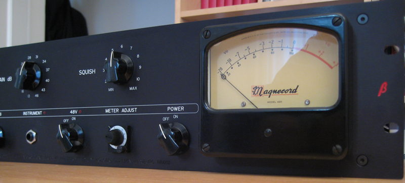
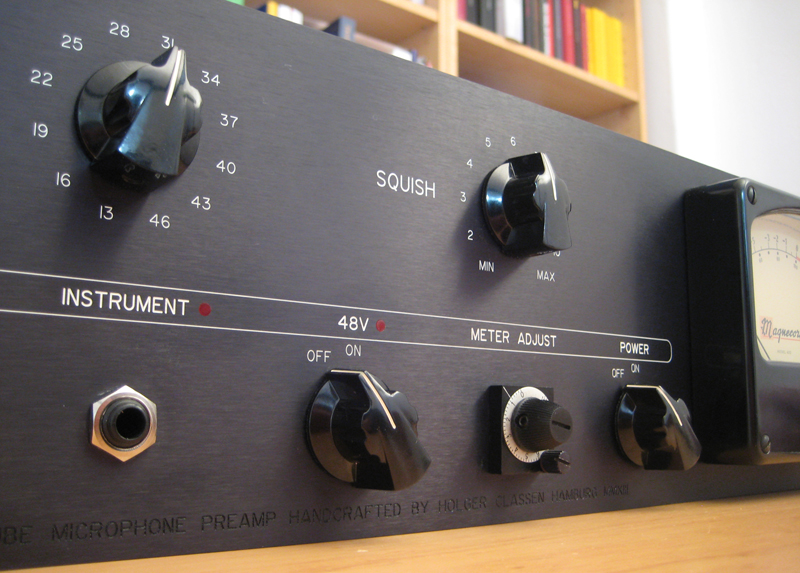
front4.jpg


front2.jpg
 
Holger said:
the signal is a metre closer to the listener.

Are you saying it's an "in your face" sound?

Top notch build Holger!

But I still have yet to understand the need for a meter on preamps.  It would distract me from making sources sound good in the studio.
 
Back
Top