


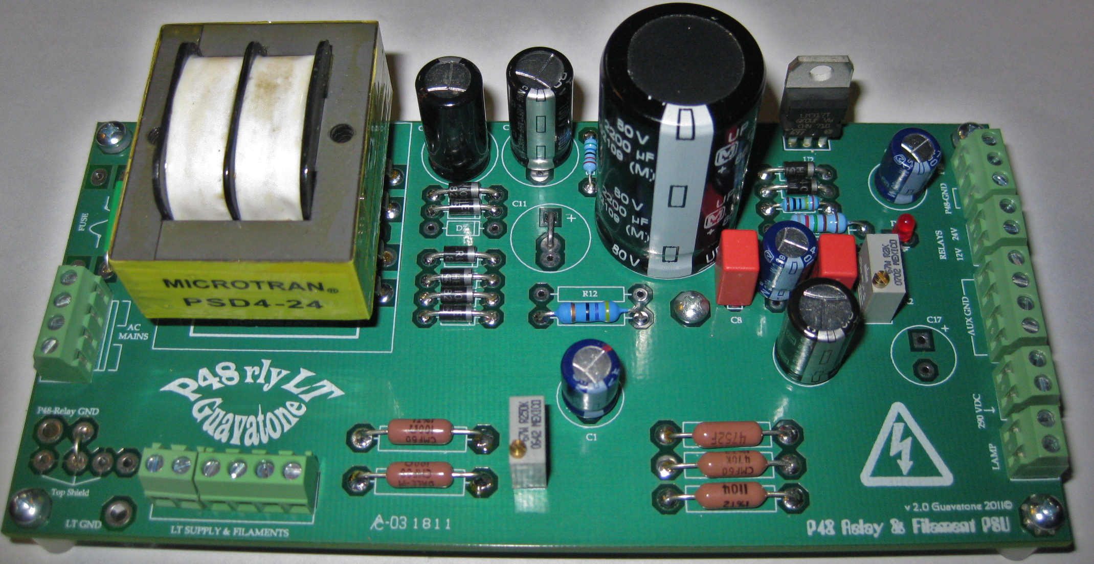
PSU for P48, Relays and balanced or elevated AC Filaments - Top Half P48 set up for voltage doubler on this photo. Most will just omit the VR1, C1 and the 3 resistors in bottom right.
Gain Switch Sources:
octopart links for sourcing the 71ADF30-01-1-AJS
https://octopart.com/71adf30-01-1-ajs-grayhill-29610379?r=sp
non-shorting can be used
https://octopart.com/71adf30-01-1-ajn-grayhill-23985?r=sp
Build Docs Folder:
https://www.dropbox.com/scl/fo/zvbyrm69vc2bs4hl7g2y1/h?rlkey=tuf668ynebcslmusgtbq2zflz&dl=0
Code:
https://www.dropbox.com/sh/g6n57y9ju6hwknz/AABrx_uyGpweCHkqwwMQi6Xja?dl=0Orange 86 preamp BOM as of October 12, 2020
https://www.dropbox.com/s/lpnrull01jx1nym/Orange 86 Preamp BOM.2020c.xlsx?dl=0
Auxiliary PS BOM for P48, relays and AC Filament supply
-Please note the Original schematic packet has the DC Heater PSU and not shipped anymore.
https://www.dropbox.com/s/nkaruxk1gdry36o/Orange 86 AuxPWR-BOM.2020b.xlsx?dl=0
Better Gain Switch Files:
Gain sw 30k.jpg
ORANGE 86 30K GAIN SW.xlsx
Note: This should be used in conjunction with No Negative feedback Compensation caps. The modification is this post:
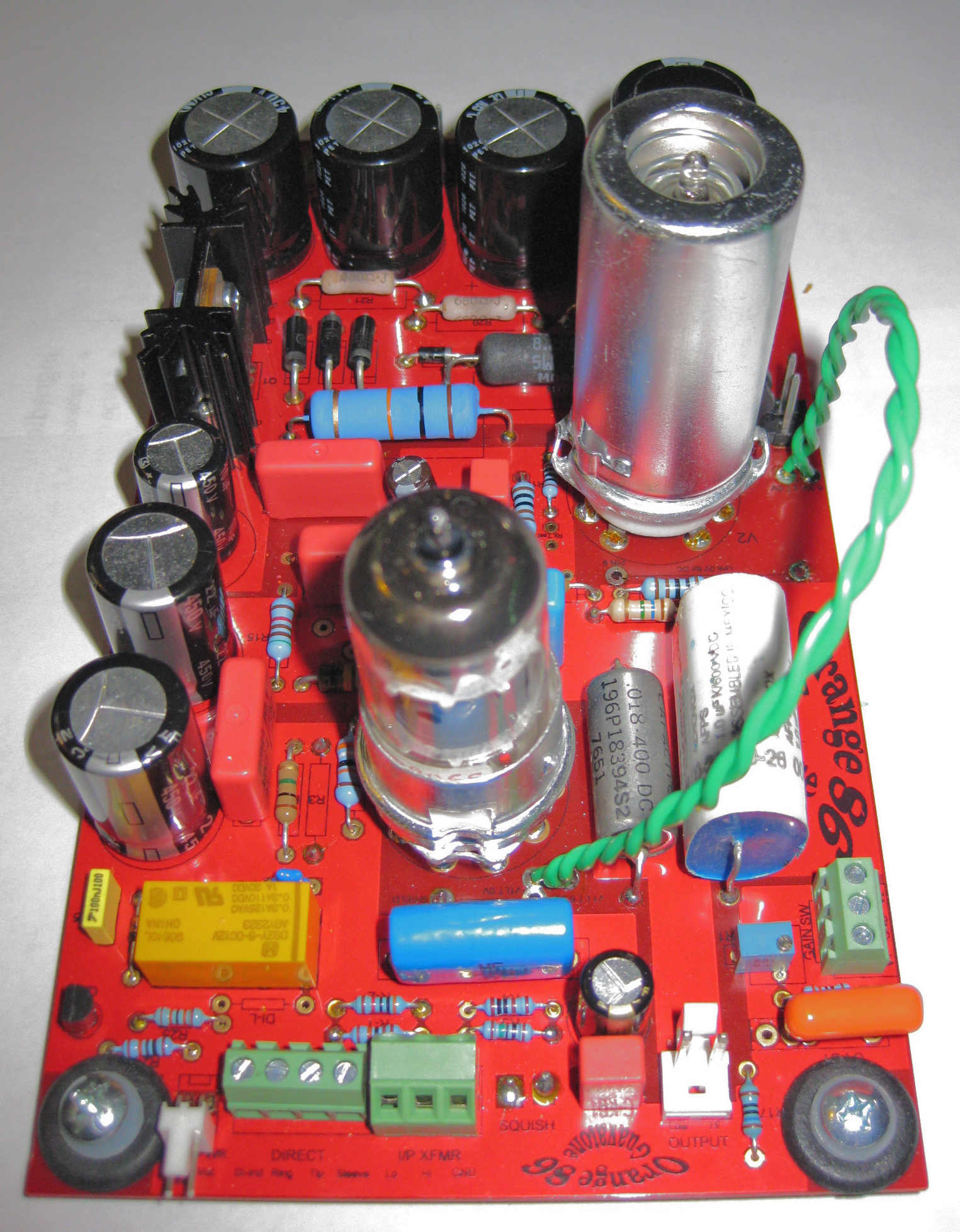
Orange 86 Build Thread
Record Engineering Development Department Type 47 inspired dual tube preamp used on well known 1960’s British recording sessions to replace the Siemens V series amps. Featuring a pentode front end and second stage military parallel triode configuration. (EF86/EF806/6267 and 6DJ8/6922/E88cc respectively). Stable, quiet, compact and efficient 290-300 VDC power on preamp PCB; linkable for stereo units. Very clean signal path with 2 high quality coupling capacitors and extra bypass cap options. Film bypass caps on cathodes. Practical NFB 12 position gain switch using an ubiquitous Grayhill PCB mount switch with 2 polystyrene caps for HF compensation. Film bypass caps on high voltage decoupling caps. 4 Auxiliary PCB’S make P48, dual PAD, DI, and GAIN wiring a breeze. 2 relays take care of automatic MIC/DI switching and Output polarity switching duties. Some engineers have really been enjoying the subtle ‘SQUISH’ compression option. Filament options for AC or DC and stage 2 tube variations like a 12V 12bh7. Tweeker’s Delight!
Power PCB sets P48 and relay power, balances Filament AC, and provides and easy route to ON/OFF indicator lamp. Optional circuit to elevate Filament ground reference. P48 doubler or trippler. Unregulated Relay/Auxiliary 12 or 24 volts.
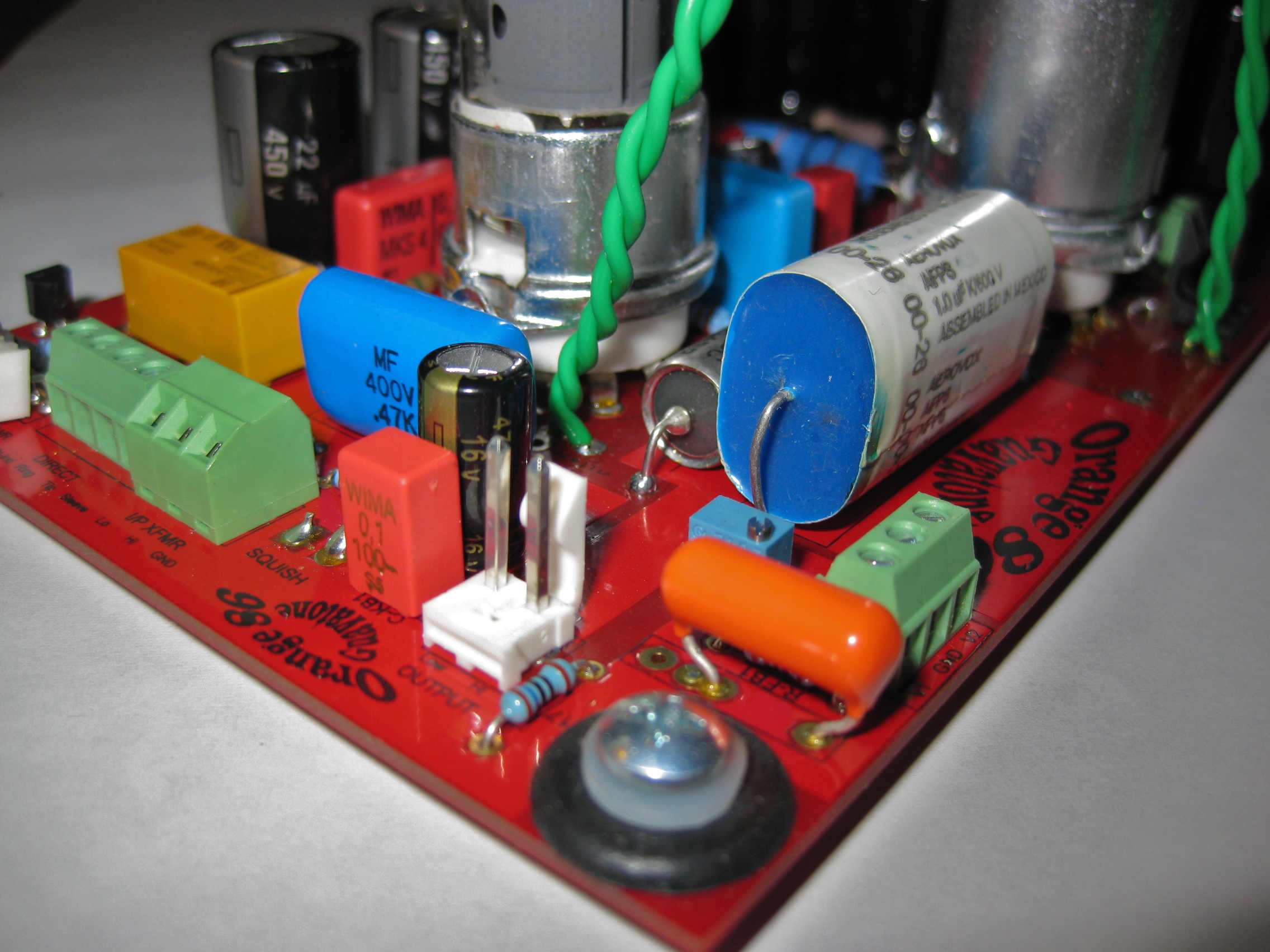
Squish Notes
The Squish is just to experiment with Compression. I forgot to mention in the build docs, but it is very important. Make sure you Jumper the Squish Pads together if you do not want it. I would start without it to make sure the preamp works,then play with it to see if it's something you like. Maybe add a pot with a switch so it can be shorted when the squish is not in use.
Insert a 500K pot wired as a variable resistor. Or use a 500K pot with a switch so that you can turn squish off and have the path go to ground to disengage it.
Pot with switch:
https://www.tubesandmore.com/products/potentiometer-alpha-audio-spst-switchor bourns: PTR902-2020K-A504 and just use one side
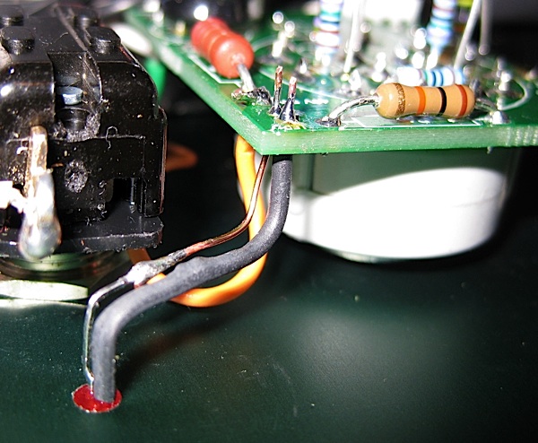
Notes on LED indicator for P48
If your LED hole is above your P48 switch it will be necessary to extend the LED's leads with some 24-26 AWG solid wire. I used some CAT-5 network cable with solid wire for one LED. Just make sure to trim LED leads or the wired bends may be on the solder joint which is never good. 24 AWG is better since it is stiffer. Strip 2 solid 24-26 AWG wire. Cut 1/2" off of LED leads. Solder solid wire to LED leads. Apply heatshrink to Positive(long lead) of LED. Bend leads appropriately. Solder to P48 PCB - Positive pad is on top and Negative pad is below. Adjust LED to proper height and apply dab glue to keep in place.
Orange 86 Constant Impedance Gain Switch
This way of varying Negative Feedback to alter the first stage pentode gain is similar to the Siemens V76 topology, just implemented differently to suit the REDD.47 circuit. We were testing some recording at 98K sampling rates and the high were sounding harsh compared to our differential tube preamp. We then tried various methods of varying gain and found this method gave best THD and frequency response through the Audio Precision. Many have found they like the full gain settings better in the REDD preamps which confirms our findings. Since with lower gain settings the impedance would be a resistive load of 10K at +40 dB and 6.4K at +34 dB, and the high frequency would extend out to 40-60 KHz (Read up on Bode plots and feedback theory, which explains this in more detail).
This Constant Impedance gain switch along with 2 capacitors solves the inconsistencies of the old gain switch. The first cap at the pentode input and R3 rolls off highs so any high frequency problems are corrected at the input, rather than in the feedback circuit. The other cap across R8 compensates for high frequency loss at high gain settings. The original switch tries to fix high frequency problems after the fact and is partly what lead us to a new gain switch in the first place.
1. Omit C-FB-1 & C-FB-2
- jumper R-FB-1 or C-FB-1
2. C-M1 - Put a 330pf ceramic COG/NPO cap from V1 grid(Pin 9) and use 1K on R3 grid stopper
-Silver Mica is fine here too and may be preferred by some. You can use a range down 220pF and
increase R3 to 5k7 to 10k if that’s what you have.
3. C-HF1 Put a 22p COG/NPO cap rated at 1KV across R8.
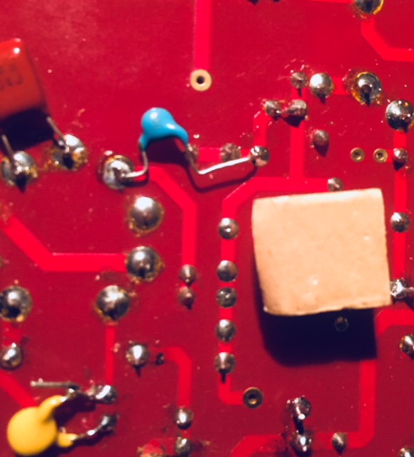
https://www.dropbox.com/s/p3jugxio9f96e8u/IMG_2269.jpg?dl=0
It takes all of 5 minutes and is pretty easy. The blue cap is the 22p and ones side goes into the valve PAD which has plenty of room and the other side goes into C3's bypass cap pad.
The Yellow cap is the 330p cap the top wraps around the lead of the 1K grid stopper and the bottom lead going into the ground pad for R2, which is not needed.
With the above complete here is the Constant Impedance Gain Switch Directions
-Above mod necessary for Constant Impedance Gain Switch
Instructions for modifying gains switch PCB to work with constant Impedance Gain Switch (photos)
https://www.dropbox.com/s/t1qgo311aq3u2fw/Gain sw 30k-Instructions.pdf?dl=0
1. Jumper R-FB-1
2. Omit these Parts
C-FB-1
C-FB-2
R-17
R-5
VR-1
3. Follow schematic of Gain Switch Connections
Here is the basic Diagram without the Gain Switch PCB:
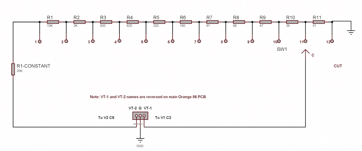
https://www.dropbox.com/s/vqzx9pvux8wq3x8/Gain sw 30k.jpg?dl=0
Here is the Gain Switch Modification diagram:
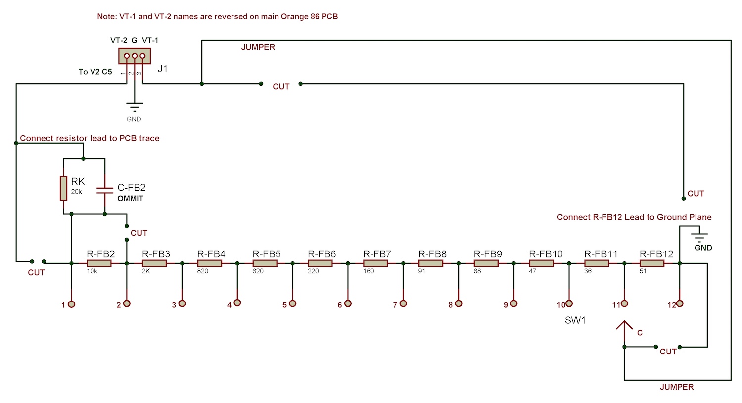
https://www.dropbox.com/s/ifymtwdoqcxtnv3/Gain sw 30k PCB mod.jpg?dl=0
My definitive termination configuration for Input transformer secondary is 130K for R-T
For DI-L a 2M-4M resistor. And omit R2. Use the appropriate R-z and C-Z depending on the transformer used.
The 130K will reflect 2K at 1KHz and 1.5KHz at higher frequencies.
Also, if you want to cut your high frequency response you can play around with the blue cap from 47p-100p for +1 dB or so from 5-10 KHz.
Fine Gain Switch +/- 5 dB Can be added to Original Gain Switch
Using these values in place of R5 and removing VR-1 and R17 pot adjustment that alters the lower feedback divider resistor. These values are from stringing series resistors together like on the gain switch. It should give a 10 dB range with 1/2 a dB between steps other than the 200R step. The Pole of a 12P switch will go to Th V1 Gain switch point. The 43R and Position 1 will go to the negative side of C2. The 36R will hang off position 12 and go to ground.
You can wire with switch from several points:
the 2 R5 PADs
R17 - provided one side meet the feedback of the main switch
or Just take it from the V1 connection on the gain switch and the other end directly to ground.
-a look at the scheme should clarify this
OTHER UPDATES
Recommend R5 or 120R and omit VR1 and R17 network. IMHO a waste of $2
R-T = 130K (list of reflected Impedance on BOM sheet)
DI-L = 2M
Omit R2
R3=1K (can't hurt and may help)
Edited and added non-Kit Part options
Yellow Highlights for non-Kit Parts for better clarity
Happy DIY-ing folks!
Last edited:
