Overkill tube pre/EQ called Drive-1. Maintenance update.

GroupDIY Audio Forum

Help Support GroupDIY Audio Forum:

This site may earn a commission from merchant affiliate links, including eBay, Amazon, and others.
revision 1.1 attached in the first post with changes to PSU transformer configurations, some typos corrected and misc. info added.

I was wondering, if my total current draw for a dual unit B+ is about 50mA (calculated from bias points of all the tubes), what should I specify the 300VAC for?

I seem to recall I read somewhere it should be about 3X the bias point current draw for a safe build.

Heater I've learned to spec so that VAC winding is used to only about 60% of the rated max, 5-6A for this project. (no core saturation, stable voltage)
 
Kingston said:
500VA! and it weights 7.7kg! That's one serious safety margin. I suppose passive burglar protection as well.

Sorry! I must have been mistaken by the title of your thread : Overkill tube pre...  ;D

more realistically, a 100VA 400V/12V transformer weights only 2.1K and cost a bit more than 50 euros...
http://fr.farnell.com/block/steu100-24/transformateur-100va-230-400v/dp/1131572

If you already have the other transformers, this may be the solution....

Still, your ideal traffo needs:
primary: 115+115VAC
secondary 1: 300VAC 200mA          60VA
secondary 2: 9VAC 5A                    45VA
secondary 3: 12-15VAC 200-500mA  ~5VA
secondary 4: 50VAC 50-100mA          5VA 

Total 6 windings and 120VA. Those guys at Audiophonics would get it custom made for you in 2 or 3 weeks for 49 euros including VAT! Cheaper than any other solution... 
I didn't tried their service yet, but it sure tempting...

Axel
 
BTW i've ordered one custom transformer from Audiophonics, still waiting for it, will report if it's any good if you're curious, because yes their prices are pretty good, now where's the itch....
 
Yes please reports from Audiophonics will be interesting, especially for any future projects.

But now I actually found a suitable transformer for the B+ part.. It was there in my stash all along! I was saving it for something - maybe a guitar amp project - but can't remember anymore. 0-220-250-300V 140mA - 6,3V 3A - 12V 300mA. That one, and a separate 9V off the shelf trafo for DC heaters and I'm good to go. PSU will be external so I don't have to care about the physical size of PSU, or proximity of PSU transformers to the audio circuits and I/O trafos.
 
Bump for an important question,

if my unit is biased to about 50mA for all the tubes (calculated from bias points of all the tubes), what should the B+ line be minimum rated for?

What is a good max current draw and overhead estimation? Double the bias point? triple even?
 
A PT rated at 100mA or more at(reasonably close to) your chosen B+ will be safe and reasonably cool. 

If you put a 200ma PT in there with the same winding rating you'll have a few extra volts to knock off the B+ feed. 

Winding voltage  may be based on whatever works out best for your chosen R values in the filtering circuit.  When there looks to be excess drop I try and keep that under 50V total.
 
Thanks.

I was worried if I had taken everything into account. That last stage is biased to 10mA, so a very loud signal might take it close to about 15mA, a point where grid current surges and sucks the stage delivering that current into blocking distortion. The rest of the stages are biased much lower, so there's not much to worry about. I guess it could be safely assumed the thing will never draw even double the bias current.

Let's call it 120mA minimum, allowing for some safety headroom for the unforeseens.
 
emrr said:
ruffrecords said:
3. The SA-70 does not do this! It is a completely different sort of NFB loop.

It does in that there is a voltage divider pot within a feedback loop; my only point.  Care to spell out the differences between the two FB variations?   I think it not so great in practice, especially at 10 dB max.  I just re-read an article about NFB written by a Gates engineer, which explores 6 different NFB methods in the context of the SA-70 circuit.   They do not elaborate, beyond showing all the different ways that will work. 

In your design the pot is in the loop and actually alters the GLOBAL open loop gain. In the SA-70 the pot is in the input arm of a shunt derived shunt applied LOCAL feedback loop. Totally different especially from the stability point of view.

Do you have a link to the article on NFB by the Gates engineer?
Cheers

Ian
 
I've never thought of plate to plate FB as local, perhaps because one sees a reduction in output level at that first plate when it is applied.  I suppose local from the point that the FB does not pass through the first tube. 

Again, I think either works in the context of 10 dB total NFB.  Run it up to a typical 20 dB+ and I would expect larger problems. 

I know long ago I mistakenly modified a V2 grid resistance to be a volume control, in an amp with V2 plate to V1 cathode NFB, and it did work, just not well.  I think the very way in which it misbehaved may be what is being sought in this design, I can't really say. 

I'm curious to bench a few things for comparison now. 
 
I've tested the filter network on bench and it is almost too smooth due to the very wide shelves. As such it allows for wide smileys only, and decent bass/high cut. I guess that serves the original purpose to aid in shaping the distortion, but less as plain EQ usage.

I've also drawn the PCB's for PSU and the actual channels already, even revised them several times. But now I have to wait till around mid January to continue. Too busy elsewhere.

If someone has a good idea where to have very sturdy PCB's made for tube projects like this, especially for prototyping, please let me know. Lukas is no longer in business and I don't quite know who to turn to.
 
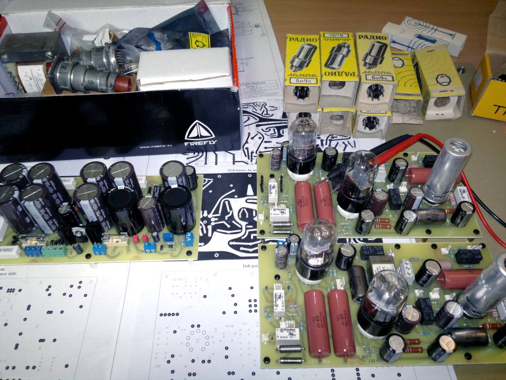
I didn't actually print these. I got help from another prodigy pro member. These are made by someone with a lot of experience and they are industrial grade 2mm material with very thick and accurate copper pour. I wanted these to be easily fixable and/or modifiable. I just love populating boards and today has been fun. Too bad almost all the rest of the steps to get this running are such a grind.
 
A drafting suggestion: take out the ~s on the DC voltages. They're small enough that they're easily mistaken for - signs, leading me to wonder at first why you were designing a plate regulator with -360V at its collector.

If necessary, you can include a note "All DC voltages +/- whatever".

Peace,
Paul
 
Hi,

If ZD1+ZD2=300V then B1+ is 300V, not 320V. B2+ is 250V.
The B+ drop circuitry will not work corectly.
LM388t is amplifier, LM338T is regulator, it's maybe just typo.
The LM338 needs more than 3V for VIN-VOUT.

Regards,
Milan
 
moamps said:
If ZD1+ZD2=300V then B1+ is 300V, not 320V. B2+ is 250V.

Hmm I copied this part of the circuit from elsewhere and they were using this "zener voltage+20V" difference as well. I thought maybe the pass-transistor somehow adds this, so I didn't question the values. Will the pass transistor follow the zener reference voltage exactly?

If so, I'll just use 160V zeners there.


moamps said:
The B+ drop circuitry will not work correctly.

What do you mean by this?

I mean, I realise the first pass transistor will have to eat a whole 160V of more voltage difference in the "low B+ voltage" setting, but I have a big cooling block and the transistor is certainly rated to handle this 10-20W of heat very generously. That MJE18004G is an impressive part. TIP50 can (barely) do it also. Sure I could upgrade the overall design so that I would also have an alternate R2 switched in that would handle some of that large voltage drop, but on this initial try the transistor has no choice but to suck it.

moamps said:
LM388t is amplifier, LM338T is regulator, it's maybe just typo.
The LM338 needs more than 3V for VIN-VOUT.

Whooops it's a typo, thanks for letting me know. But no, the regulator doesn't need more than 3V difference between in and out. In fact 3V (close to the minimum) is optimal. with 3-4A going through it even 3.5V difference would produce significantly more heat. The regulator is difficult enough to keep cool with just 3V difference with this much current. I've used this heater supply many times in the past already.

pstamler said:
If necessary, you can include a note "All DC voltages +/- whatever"

I'll update these bits as well, thanks
 
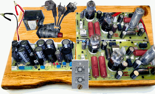
I now have everything except the case, but can't order it for about a month (life gets in the way). Can only wait now, but at least I can look at these pretty populated PCBs and try to imagine what it sounds like. :(

the agony!

populated1-web.jpg
 

Latest posts

Back
Top