;D
You are using an out of date browser. It may not display this or other websites correctly.
You should upgrade or use an alternative browser.
You should upgrade or use an alternative browser.
Overkill tube pre/EQ called Drive-1. Maintenance update.
- Thread starter Kingston
- Start date


Help Support GroupDIY Audio Forum:
This site may earn a commission from merchant affiliate
links, including eBay, Amazon, and others.
Kingston
Well-known member
PRR said:> everything except the case
Bah, who needs case? Nail to a board.
hahaha!

I thought of that to be honest, but with these currents and voltages I'm slightly concerned about safety. Mains fuse and safety ground will hang by a thread. I might be able to go with that but there's our cat roaming around freely. He won't jump on the table while I'm working on it, but during the night he will inspect my solder joints several times. There's a decent drain resistor set up since the PSU will be external, but maybe I screwed up somewhere and the cat finds it first.
Kingston
Well-known member
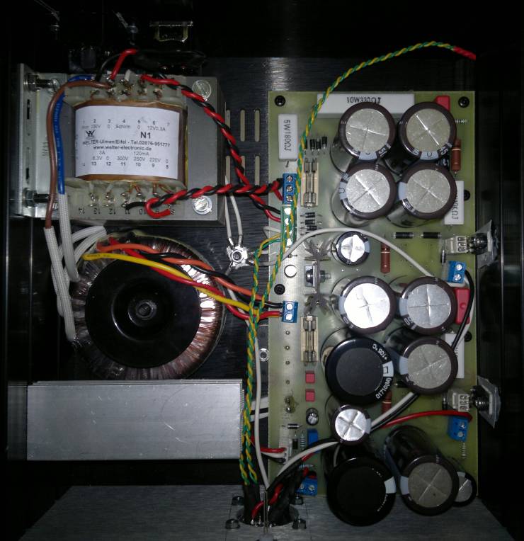
Got tired of waiting and tested a couple of things today. Everything in the PSU with dummy loads. All estimated values came out perfect. Even the zeners, which were a bit of a mystery. The zeners in B+ side (150V + 150V) came out 320V which I had estimated, but don't quite know why. Maybe they are 5% quality.
Everything worked fine except my switchable B+ zener configuration. I only tested the 270VDC to 120VDC setting. As soon as I flipped the switch, *pop* goes the weasel. Well, only zener and transistor. That's definitely not gonna work then, and some people already warned that it wouldn't, but of course I had to try it anyway. Curiosity fried the transistor! Wonder what killed them.
If someone knows how to make an easy switchable regulated B+ that actually works, I'd love to know how.
The really easy way out would be just to switch the PSU's R2 between 220-330ohm(somewhat optimal) and about 1.5k - 2k. Dropping 150V with many wasteful watts of course. That skips the regulator completely but it's already a very very stiff passive PSU so it's a non-issue.
Might be too trivial of a solution, but you can obviously switch safely with the power disengaged. So either use the power switch or an additional switch only for the B+ (double pole before the rectifier definitely recommended). Downside is you would have to wait until the caps are drained, but that should only be a few seconds with the tubes in and all those parallel resistors. Maybe install a led indictator for that purpose.
Kingston
Well-known member
I thought of that, but it sounds too much like a very literal "kill switch" for the PSU when being misfired. Yes the PSU drains to safe voltage in about 5 seconds, but still plenty of time for a *snap*. Sure, I could make this safer with timers and relays but that would be a hack of a hack already.
For testing your solution is fine of course, but I want to put this on the front panel.
For testing your solution is fine of course, but I want to put this on the front panel.


$15.98
$16.98
Gikfun Upgraded USB Mini Amplifier Electronic Transparent Stereo Speaker Box Sound Amplifier DIY Kit for Arduino EK1918
Gikfun_Official_Store


![Soldering Iron Kit, 120W LED Digital Advanced Solder Iron Soldering Gun kit, 110V Welding Tools, Smart Temperature Control [356℉-932℉], Extra 5pcs Tips, Auto Sleep, Temp Calibration, Orange](https://m.media-amazon.com/images/I/51sFKu9SdeL._SL500_.jpg)


Jonte Knif
Well-known member
If someone knows how to make an easy switchable regulated B+ that actually works, I'd love to know how.
I guess you want to keep it simple, i.e. one pass transistor of FET?
I would do like this:
-FET, for example IRF820
-zener "reference" for the highest voltage.
-ladder "attenuator" from that voltage with some nice plastic bodies rotary.
Use FET, it is so convenient to not have to care about grid current.
Put an RC filter after the ladder attenuator. Use long time constant, so that in every case your "drain" resistors can empty any caps after the fet faster than your time constant for grid voltage. Around 220k and 33u perhaps. And of course it is still a good idea to put zeners across G-S and D-S, perhaps 300V and 9,1V. (That D-S zener(s) 5W). Then you shouldn't be able to break anything.
-Jonte
Kingston
Well-known member
Thanks Jonte! I think I will draft that to a next project. This kind of ladder with very slow RC would have worked for the plain "TIP50" plan as well. I think as long as the reference potential doesn't abruptly change it will work. With the way I did the switch the immediate change charges the zener way too fast. There must be plenty watts in that sudden 100-150V potential difference, enough to kill the zener which was "only" 5 watts. At least that is my freestyle theory.
Kingston
Well-known member
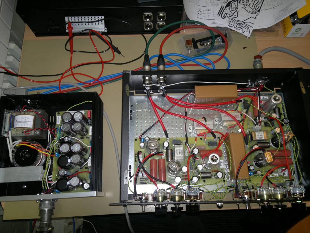
I have been wiring all weekend and barely made a dent.
This thing has more wire any of my previous projects. It's too easy to copy and paste them for the schematic. Then comes the time when you have to put six switches and four pots/rotaries on the front panel.
Times two!
Aih!
And I absolutely hate metal work too. Wish I could completely outsource it but that's never gonna happen.
Kingston
Well-known member
A success on the first try. ;D
It's not quite the "cream come true" mellow sound and the reason is clear as daylight now that I look at the schematic and actually hear it. It's a high gain guitar preamp! I mean, of course it is and why didn't I see that earlier. It's just interfaced clean to the balanced world. And when I say clean I mean 10hz-35khz +-0.5dB. Distortion at the cleanest setting is 0.2-0.3% (RMAA blasted at AD/DA 0dBFS levels ie. loud, not a +4dBU reference test). Obviously there is headroom.
I drafted in that output stage feedback but it's not going on the front panel and will be removed from the schematic. What would be the point with the above figures?
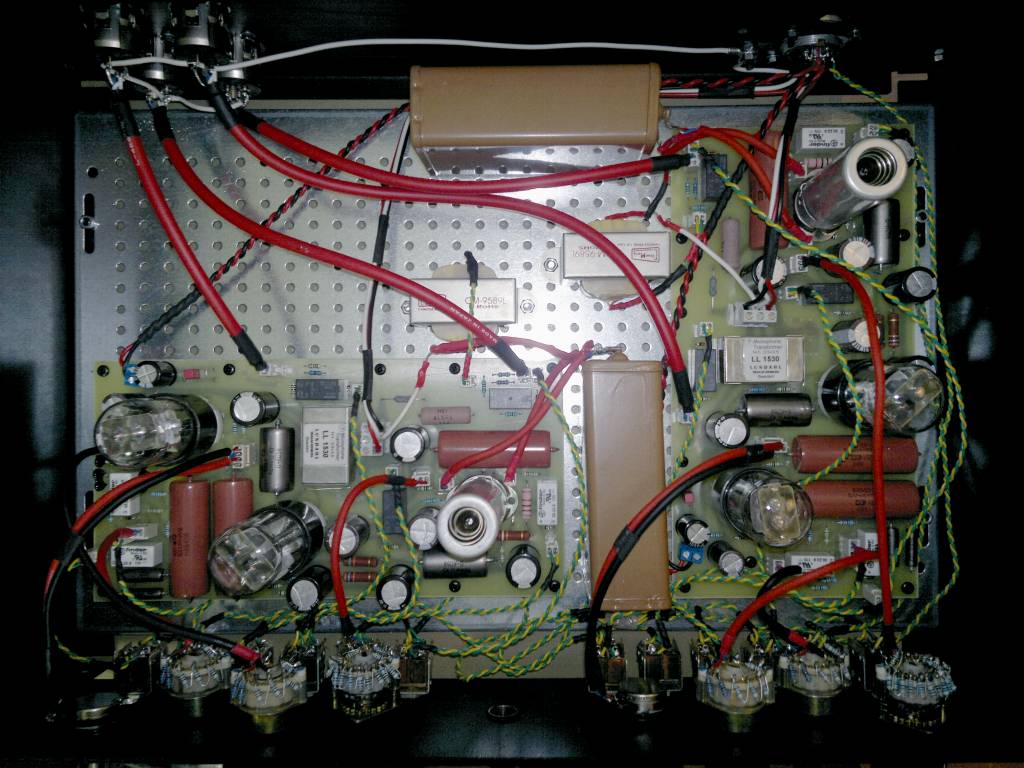
Easily the best mic preamp I have. The best I've ever even heard, but I designed it so I'm biased. The "no cathode bypass" setting is such a strangely articulate midrange and stereo image I haven't heard it before. Acoustic guitars will record like a dream. The Lundahl input of course gets some points for that as well.
That's was the clean setting.
Flip in the bypass caps(about +12dB of gain), boost bass, cut highs, and first it starts to softly crumble (but not fart!). Bass authority, drum bus and vocal low/mid grunge like I meant it to be. "sly and the family stone - family affair", "Little Richard - Tutti Frutti" and "Percy Sledge - When a Man Loves a Woman". All there! ;D
But move on to highest gains and we're talking Soldano lead channel amounts of distortion. Lovely!
I didn't expect it would explode like that! It really does scream like the better more articulate boutique guitar lead preamps. By accident. I didn't see that coming. Fun! I have two high powered super lead channels now! What incredible range. At this point yesterday at home I went "Muahahahahaha!" from sheer happiness.But it's also somehow more controlled than lead channels. I think it's due to the regulated B+ which is uncommon in guitar world. I just adore the setting when it really boosts the bass and cuts the highs and the distortion/overdrive added the lost highs back in a screaming creamy mess. Had to listen to hours of music on this messy setting.
I have something very unique here that's for sure. The musical equivalent of this.

Some additional points,
1. With the tube biasing switches and it was quickly clear that hot bias sounds better and softer when overdriven. I compared resistances between optimal (from plate curves), double the optimal, and half the optimal. So I will update the halved values into the schematic. Switching between bypass cap and no bypass does not pop by the way. Just a +12dB of gain and a slight change of distortion characteristics.
I also found a good design rule now that this amp allows great range between clean and dirt. If unsure about certain setting/bias/cap/etc. drive it to mad distortion, find the best sound. This will sound best clean as well.
2. I will definitely add in the low B+ setting, let's say 150V. It'll be fun to hear the amp lose control.
3. That PSU block runs really hot. I may have to make some messy changes there.
4. Sorry for the bad quality phone camera images. Now I have to design a front panel for this.
5. 50hz hum could be 10dB lower. Probably something to do with B+ grounding points. I included many for experimentation with the layout so I'm not worried.
6. Tubes seem to match strangely well. I knew 6n6p's are generally stellar, but it seems so are the 6N8S(6SN7). Even at the very high gain/distortion they match. And these are just the first ones I popped in. I thought this wasn't supposed to happen with no feedback. I guess the Soviet Military knew what they were doing. The 6N9S(6SL7) tone stacks are of course swimming in feedback but seem to perform generally well. Later when I can afford it I intend a shootout between these and the western equivalents.
Are you planning to add some sort of switchable band-limiting filtering (f.e. bandpass) - or f.e. some RC net in parallel to the OT because of that extended dist. range?Kingston said:But move on to highest gains and we're talking Soldano lead channel amounts of distortion. Lovely!
Kingston
Well-known member
Fixed the 50hz bump. It was as I guessed, a bad choice of chassis ground with B- combo. I had included plenty of other taps for debugging and one of them delivered a noise floor as black as a black mans cape. It's strange how much this varies between layouts.
Looks like I have to do some more tube biasing vs. distortion evaluation. Seems biasing them hot isn't automatically a better sound. It's in fact more linear to a point, then a very asymmetric sharp break up point (blocking distortion). I'll do something drastic like socket the bias resistors and do a better evaluation.
Not a bad idea. The scream can get a little too sharp occasionally. Even a passive balanced low pass filter after output transformer would help a bit. I'll think about it. But I have quite many EQ's elsewhere for this already so it might not happen.
lassoharp, time for sound clips is not yet. This is still on the debugging table and low plate voltage tests etc. coming.
Looks like I have to do some more tube biasing vs. distortion evaluation. Seems biasing them hot isn't automatically a better sound. It's in fact more linear to a point, then a very asymmetric sharp break up point (blocking distortion). I'll do something drastic like socket the bias resistors and do a better evaluation.
tv said:Are you planning to add some sort of switchable band-limiting filtering (f.e. bandpass) - or f.e. some RC net in parallel to the OT because of that extended dist. range?
Not a bad idea. The scream can get a little too sharp occasionally. Even a passive balanced low pass filter after output transformer would help a bit. I'll think about it. But I have quite many EQ's elsewhere for this already so it might not happen.
lassoharp, time for sound clips is not yet. This is still on the debugging table and low plate voltage tests etc. coming.
Kingston
Well-known member
The tone stack is a new sound to me. Very different to passive EQ's obviously. Almost boring because the shelving is so tight and controlled. very usable nevertheless. I just wish I had thought of an option for three cut off points for both bass and treble shelves. Now I have two (through relays) and it's hard to choose what these points should be. I think these will be socketed for better evaluations as well.
On the "air" frequencies, post 10khz, it seems caps have a large effect on sound. Silver micas sound quite harsh, while NP0's and C0G's sound very smooth.
On the "air" frequencies, post 10khz, it seems caps have a large effect on sound. Silver micas sound quite harsh, while NP0's and C0G's sound very smooth.
Matador
Well-known member
The latest pictures show 6 multi-position switches with resistors, and I don't see those on the schematics. Are there multiple projects being shown in the photos? I'm confused.... ;D
Kingston
Well-known member
They are 2X 100k log and 4X 250K linear pots done as stepped rotaries. Definitely all shown on the schematic.
Same for all the relays because technically they are nothing but DPDT switches. I purposefully neglect to mention build details like this in a design schematic.
Same for all the relays because technically they are nothing but DPDT switches. I purposefully neglect to mention build details like this in a design schematic.
Matador
Well-known member
Kingston said:They are 2X 100k log and 4X 250K linear pots done as stepped rotaries. Definitely all shown on the schematic.
Same for all the relays because technically they are nothing but DPDT switches. I purposefully neglect to mention build details like this in a design schematic.
Ahh...I see, VR1-VR4. Why stepped rotaries? Did you want something other than regular linear and audio tapers?
Kingston
Well-known member
For 250k linears the only reason for rotaries was that I could not find a center detented pots that I could trust. So I built them, 5 steps each direction. For the 100k log the reason was control and reliability. I can use my own scales that I've come to like (http://homepages.tcp.co.uk/~nroberts/atten.html) and I have steady access to Elmas. I like the fact I'm using the same rotaries as the International Space Station! The first 100k log pot is kind of non critical so I just used some cheap Piher pot there.
mylesgm
Well-known member
Will you be making the schematic available for a self etch experiment? sounds like a fascinating project I'd love to tackle and I'm sure others would too...
Kingston
Well-known member
Sure, I will make them available. The PSU especially is very flexible and easy to use. I actually designed so that I can use the exact same layout for my future vari-mu project.
But I want to test some modifications and features before any public release. I also seem to have developed strangeness on one channels cathode switchers that needs to be solved.
But I want to test some modifications and features before any public release. I also seem to have developed strangeness on one channels cathode switchers that needs to be solved.
Similar threads
- Replies
- 22
- Views
- 2K
- Replies
- 24
- Views
- 6K
- Replies
- 3
- Views
- 1K
Latest posts
-
-
AKG Perception P220 to Neumann u87 5 min mod ( p200, p100, p400, p420? )
- Latest: Masiusima13
-

-
-

-
-