P2P Redd 47 - a few questions

GroupDIY Audio Forum

Help Support GroupDIY Audio Forum:

This site may earn a commission from merchant affiliate links, including eBay, Amazon, and others.
The simple HPF constituted by a series cap (with or without a damping res) can be tuned higher by decreasing the value of the cap. You must experiment to adjust the proper value. The problem ther is that this type of filter can be anything from first to second order, depending on the actual inductive and resistive parts of the impedance. If the input behaves like a pure resistor, the frequency is inversely proportional to capacitance, if it was purely inductive, the frequency would be inversely proportional to the square -root of the capacitance. Since it is actually a mix pf resistor and inductor, the relationship is somewhat unpredictable.

Keeping the filter before the input transformer, would it make sense to make it balanced? Like this...

gadget-2.jpg


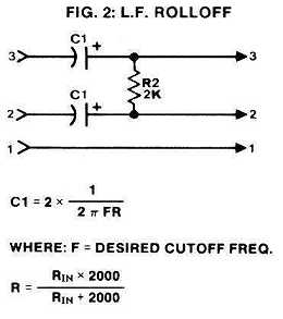
If so, would 2K be a good value to use? I'm assuming the cap value would still need to be adjusted because of the inductance of input transformer, but would the formula (in the image) be a good place to start?
 
great question,

very open minded

zobel on the input

use a long mic cord,

divide stray C by the input ratio,

in other words, if you have a 1:10 input xfmr,

divide sec input C by 10

so you would adjust your values accordingly,

not a math freak so do not know if your formula is rigfht,

how ever, just experiment,

core loss is there,

a zobel sucks juice to flatten the curve so input current must be watched.

 
Attached is an input circuit I've worked up.

My idea with the DI input jack is that the sleeve and ring will be connected with a standard 1/4" mono plug -- thereby connecting the 1M resistance to ground. Switchcraft's N113BX seems like a good choice for this.

Hopefully, the HPF values are close. I'm planning to adjust the caps after testing the preamp.

I decided to go with a -20dB pad instead of -18dB only because the impedance seemed to work out a little better.

The 48V circuit was found here: http://sound.westhost.com/project96.htm

Please post any suggestions or concerns.

Thanks!
 

Attachments

  • redd-input-v1.png
    redd-input-v1.png
    66.3 KB · Views: 328
Am I correct in thinking that the primary of the output transformer is protected from DC by C5?

I ask because the folks at Edcor tell me they are willing to make a run of 7:1 transformers for a very affordable price. They also said the transformers would not have a "butt stack", but I don't think that's necessary for the REDD.47 circuit. Is this correct?

Thanks!
 
earthsled said:
Attached is an input circuit I've worked up.

My idea with the DI input jack is that the sleeve and ring will be connected with a standard 1/4" mono plug -- thereby connecting the 1M resistance to ground. Switchcraft's N113BX seems like a good choice for this.
You could leave the 1Meg permanently. If you want to be exacting you could increase the 97k to about 105k. [/quote] Hopefully, the HPF values are close. I'm planning to adjust the caps after testing the preamp. [/quote] I bet you'll have to.
  I decided to go with a -20dB pad instead of -18dB only because the impedance seemed to work out a little better.
Again it illustrates the mathematically almost impossible task of designing a mic pad of less than 20dB attenuation.
 
You could leave the 1Meg permanently. If you want to be exacting you could increase the 97k to about 105k.

This would simplify things. Is the idea to have 105k in parallel with 1Meg and add up to about 97k?

I bet you'll have to.

The EMI documents suggest cap values in the range of 0.75uF to 1.8uF for 50Hz. Perhaps something smaller like 0.68 or 0.56uF would be a better starting place? Also, should I stick with the 1k res, or is there a better value?

Thanks!
 
earthsled said:
You could leave the 1Meg permanently. If you want to be exacting you could increase the 97k to about 105k.

This would simplify things. Is the idea to have 105k in parallel with 1Meg and add up to about 97k?
Yep!
The EMI documents suggest cap values in the range of 0.75uF to 1.8uF for 50Hz. Perhaps something smaller like 0.68 or 0.56uF would be a better starting place? Also, should I stick with the 1k res, or is there a better value?
1k is too low for my taste; it won't do good on most dynamic mics (ribbon in particular). The reflected impedance on the primary is about 2k, which I consider to be the minimum acceptable for dynamic mics. Try first without the 1k res, you may see a slight hump in the frequency response; that can be a nice artefact, lightly boosting frequencies right above cut-off. Then you can experiment with different values; looks like 2k should give Butterworth response (actually it depends on the primary inductance, which I reckon about 3H).
 
1k is too low for my taste; it won't do good on most dynamic mics (ribbon in particular). The reflected impedance on the primary is about 2k, which I consider to be the minimum acceptable for dynamic mics. Try first without the 1k res, you may see a slight hump in the frequency response; that can be a nice artefact, lightly boosting frequencies right above cut-off. Then you can experiment with different values; looks like 2k should give Butterworth response (actually it depends on the primary inductance, which I reckon about 3H).

David Geren at CineMag was nice enough to measure the primary inductance of a CMMI-7C. He says that they don't publish this information because there is some variance with the value, but one off the shelf measured 2.3H. So with this inductance and a 2k resistor, what cap value would be recommended to start with for a HPF between 80 to 100Hz?
 
You don't want the 200R there.
The sum of your generator's output impedance and an additional res in series should make 200 ohms.
The 2k res should be made variable or AUT, depending if you want the hump or not.
 
Correct regarding source impedance.
Not correct regarding shunt resistor.
You have the pot connected as a pot, i.e. a voltage divider. You need to connect is as a rheostat (variable resitor), that means one side of the primary goes to one end of the pot, the other goes to the wiper. You should use a 5-10k pot, because I think you may like the effect of relieving the load there.
 
Great. Thanks! When I get to ordering input transformers I'll post the test results.

Here's my output circuit so far...
Any issues here?
 

Attachments

  • redd-output-v1.png
    redd-output-v1.png
    31.1 KB · Views: 194

Latest posts

Back
Top