P96DI & A72DI - Passive and Active Di Boxes in Business Card Format

GroupDIY Audio Forum

Help Support GroupDIY Audio Forum:

This site may earn a commission from merchant affiliate links, including eBay, Amazon, and others.

Kevin

Well-known member
White Market Member
Joined
Dec 15, 2009
Messages
132
Location
Germany - Chemnitz
Hi Friends
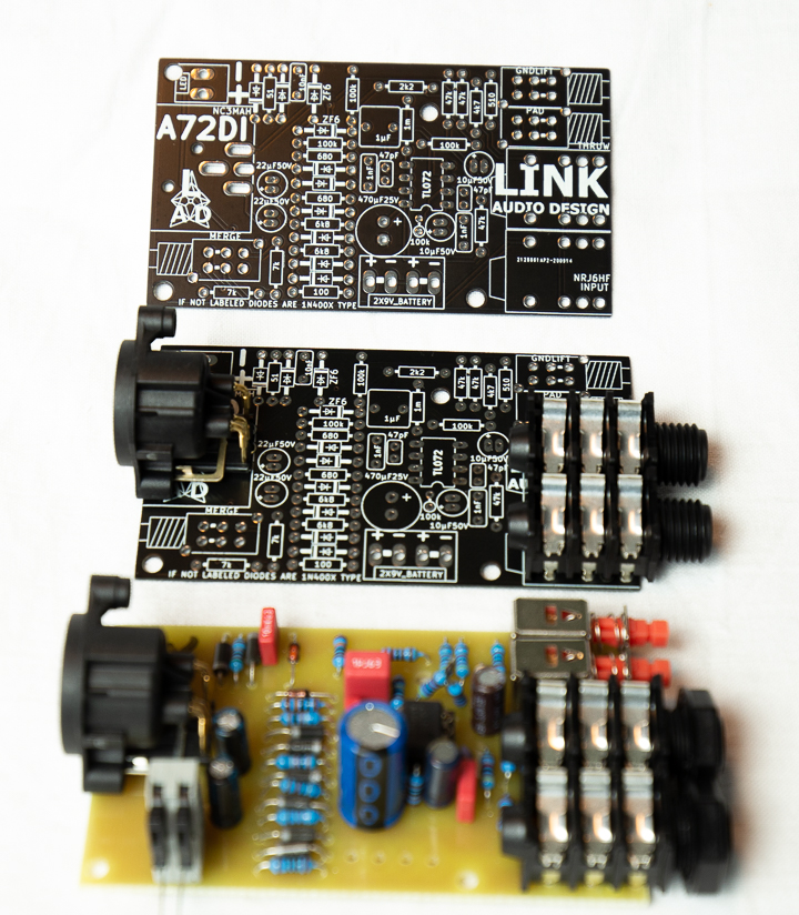
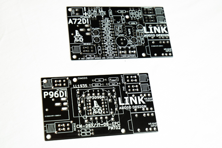
Since the last weeks i'm designing different DI Boxes in business card Format
8puz98x7.jpg

qn8p467e.jpg

r6ew3hsa.jpg


Active DI Box works with easy to get standard electronics parts.
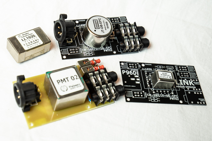
The passive Version works with different High End Transformators
Lundahl LL1935
Jensen JT-DB-EPC
Pikatron ÜP3096M
Cinemag CM-DBX
Palmer PMT02

Both DI Boxes have An Pad, GndLift and Merge Switch. Active Version can run on 2x9V Battery. Passive Version have a Polarity Switch.

I also did comparison with different DI Boxes to find out how different they sound, the difference in Level

P96DI Lundahl LL1935 -> 0.0dB
P96DI Jensen JT-DB-EPC -> -1.7dB
P96DI Pikatron ÜP3096M -> -3.9dB
P96DI Palmer PMT02 -> -0.2dB
A72DI -> +7.0dB
Bo Hansen -> +7.2dB
Behringer DI 400 -> +0.6dB

Sound samples can be found here
https://soundcloud.com/linkaudiodesign/sets/di-box-comparison
Boards available in my White Market Thread or with every bigger order one is for free ;)

White Market Thread
https://groupdiy.com/index.php?topic=76303.0

All Build Info(BOM,Schematic/Overlay/Stepbuild) will be avaivable under this link
https://docdro.id/FRChuxO

Parts for the units
passive one

INPUT,THRUW NRJ6HF 2xNRJ6HF
X1 NC3MAH 1 x NC3MAH
T1 JENSEN 1 x CM-DBX/JT-DB-EPC
T2 LUNDAHL 1 x LL1935
T3 PALMER 1 x PMT02
T4 PIKATRON 1 x UP3096M
RPAD1 0207_10C 1 x 4k7
RPAD2 0207_10C 1 x 510R
RFGNDLIFT1 0207_10C 1 x 51R
RPAD3,RPAD4 0207_10C 2 x 7k/6k8
C1 C050-075X030 1 x 10nF
GNDLIFT,PAD,180°,MERGE ALPHAMINIDPDT 4 x ALPHA SWITCH


active one

R8 0207_10C 1 x 100k
RPAD6 0207_10C 1 x 4k7
R7 0207_10C 1 x 100R
R9,R12,RPAD2 0207_10C 3 x 100k
R10 0207_10C 1 x 1m
R11,R13,R2 0207_10C 3 x 47k
R14,R15 0207_10C 2 x 680R
R17,R18 0207_10C 2 x 6k8
RFGNDLIFT1 0207_10C 1 x 51R
RPAD1 0207_10C 1 x 510R
RPAD3 0207_10C 1 x 2k2
RPAD4,RPAD5 0207_10C 2 x 7k/6k8
PAD,GNDLIFT,MERGE ALPHAMINIDPDT 3 x ALPHA SWITCH
C7,C4 C025-050X025 2 x 47pF
C10 C050-075X030 1 x 10nF
C14,C15 C050-075X030 2 x 1nF
C1 C050-075X080 1 x 1µF
C8,C9 CE-020X050 2 x 22µF50V
C6,C2 CE-020X050 2 x 10µF50V
C5 CE-035X100 1 x 470µF25V
IC3 DIL08 1 x TL072
D1,D5,D6,D7,D8,D11,D2 DO41-10 8 x 1N4005
D4,D9 DO41-10 2 x ZF6.2
LED KK-156-2 1 x LED
2X9V_BATTERY KK-156-4 1 x KK-156-4
X1 NC3MAH 1 x NC3MAH
INPUT,THRUW NRJ6HF 2 x NRJ6HF
 
Hi Frans
the active ones work with 1M Ohm input imepance, but you can use also line signals with them. there is a 20db pad working for that.
The input impedance with an transformers depends on the transformer used, also the maximum level.
Hope that helps
 
The active one works with phantom or two 9V Block batteries. the jack in the input activates the battery/ phantom power also enables the di box ;)
 
Kevin said:
The active one works with phantom or two 9V Block batteries. the jack in the input activates the battery/ phantom power also enables the di box ;)

Thank you so much Kevin,
is it possible to modify the input of the Active DI for 10Mega input impedance?
I would like to use that with some piezos.

Thank you so much
 
it fits in Hammond 125B Case but not perfectly. still need to do off board wiring
I'm working on a full metal case for this DI boxes. hopefully i get them this year ;) then i can offer also cases ;)
 
Whoops said:
Thank you so much Kevin,
is it possible to modify the input of the Active DI for 10Mega input impedance?
I would like to use that with some piezos.

Thank you so much

Hi, Kevin did you have a chance to read my message?

Thank you
 
I don't see a problem why they don't should together with piezos. But lets look at the shematics and you will find the solution by looking for non-inverting op-amp input resistance and cahnge some values in the DI Box. that shouldn't be a problem. i would defintly go for R8 and R12, but check if you would change other values!
 

Attachments

  • Screenshot 2020-12-09 164442.png
    Screenshot 2020-12-09 164442.png
    30.6 KB
Kevin said:
I don't see a problem why they don't should together with piezos.

They will work, but for most piezos 5 to 10 Mega input impedance provides a better load than 1mega

Kevin said:
But lets look at the shematics and you will find the solution by looking for non-inverting op-amp input resistance and cahnge some values in the DI Box. that shouldn't be a problem. i would defintly go for R8 and R12, but check if you would change other values!

What would you advise to change and what values to have the input impedance at 10 mega?

Thank you so much Kevin

Cheers
 
Whoops said:
They will work, but for most piezos 5 to 10 Mega input impedance provides a better load than 1mega

What would you advise to change and what values to have the input impedance at 10 mega?

Thank you so much Kevin

Cheers

As i said before please check the schematics on your own and go breadboarding and testing like we all do if want something special and want to modd something how we need ;)
I added the schematics to the last post of mine, you can use it to modify and test how you can change the input impedance. and then my board will also still work just with different values ;)
And as i said check for "Non-inverting operational amplifier" and learn about input impedance. with about more then 4700 posts you should be a guru in electronics and that will be a easy task for you! ;) ;)
 
Kevin said:
with about more then 4700 posts you should be a guru in electronics and that will be a easy task for you! ;) ;)

No I'm not any electronics guru Kevin, I'm a professional mixing and mastering engineer that does audio electronics as an hobby and I also like to fix stuff and do the maintenance in my own equipment.
I have no electronics background or former education in that area, what I know I learned over here so I'm sorry but I don't have the knowledge to modify the input impedance on my own.
Your active DIs look nice congratulations for your work, I would like to use them Live with some bands but needed the 10mega input impedance.

Thanks anyway
Best regards
 
Kevin said:
I don't see a problem why they don't should together with piezos. But lets look at the shematics and you will find the solution by looking for non-inverting op-amp input resistance and cahnge some values in the DI Box. that shouldn't be a problem. i would defintly go for R8 and R12, but check if you would change other values!

I think I see a few issues with that schematic ? I looked at the one in the linked site and that is more clearly drawn but:

There's a connection shown from the output of the first op amp stage (Pin 1) to the 47K resistor going to ground from the 10u cap on the inverting input. This shorts out the feedback R//C giving a simple unity gain buffer stage. Is this intended ?
680R build out resistors - seems rather high value ?
Deliberately placing 1nF caps directly on op amp outputs ? (C14 C15)

Back to Whoops question on the input Z and increasing it - it has nowhere near 1M0 input impedance.
Why would you be looking at R8 R12 in conjunction with that. Look at RPAD2 RPAD3 R10 R11.
 
Hi Newmarket
thanks for asking on the Schematic design.
Newmarket said:
There's a connection shown from the output of the first op amp stage (Pin 1) to the 47K resistor going to ground from the 10u cap on the inverting input. This shorts out the feedback R//C giving a simple unity gain buffer stage. Is this intended ?
I used mostly a basic schematic of LA Audio DI2. In that schematic they have an added unbalanced output. problem with that. the level isn't the same like Input/Thruw. So I cutted that out. They used a 11k resistor at that point. But overall you need to say that we have virtual ground in that schematic so that resistor is also part of the virtual ground network.
Newmarket said:
680R build out resistors - seems rather high value ?
I also tried 150R and 330R but the measurments weren't that good than 680R.
Newmarket said:
Deliberately placing 1nF caps directly on op amp outputs ? (C14 C15)
The 1nF is a kind of High Cut Filter - it works like in MHz and Ghz area for reducing HF Problems - you won't have that problems with transformers.
Newmarket said:
Back to Whoops question on the input Z and increasing it - it has nowhere near 1M0 input impedance.
Why would you be looking at R8 R12 in conjunction with that. Look at RPAD2 RPAD3 R10 R11.
Yeah but R8 and R12 are also part of the Impedance conversion of an opamp. So they are also part of that process. Yeah true changing RPAD2 and RPAD3 can change also a lot. Why would you change R11? thats defintely part of the Virtual Ground?

Best
Kevin
 
Kevin said:
Hi Newmarket
thanks for asking on the Schematic design. I used mostly a basic schematic of LA Audio DI2. In that schematic they have an added unbalanced output. problem with that. the level isn't the same like Input/Thruw. So I cutted that out. They used a 11k resistor at that point. But overall you need to say that we have virtual ground in that schematic so that resistor is also part of the virtual ground network. I also tried 150R and 330R but the measurments weren't that good than 680R. The 1nF is a kind of High Cut Filter - it works like in MHz and Ghz area for reducing HF Problems - you won't have that problems with transformers. Yeah but R8 and R12 are also part of the Impedance conversion of an opamp. So they are also part of that process. Yeah true changing RPAD2 and RPAD3 can change also a lot. Why would you change R11? thats defintely part of the Virtual Ground?

Best
Kevin

Hi. I looked up that DI2 schematic. That makes sense in that it has a switch to set the first stage gain to unity or x10. But your schematic indicates that the unity gain setting is hardwired so the 100K//47p elements never come into play.
get that you might want to filter out rfi - but putting capacitors directly on the opamp output pins seems to be inviting instability problems ? Is there not a resistor between the output pin and the capacitor ?
re R8 R12 - Whoops was wanting to alter the input impedance. R8 and R12 do not have any real role in this - in particular R12 is around the second op-amp stage. The impedance conversion function is a function of the op amps but it does not define the input impedance.

wrt Input Impedance I guess that wrt 1M0 you are thinking of R10 1M0 (it wasn't clear to me that this was 1M0 due to the annotation of 1m) but I can see it clearly on the DI2 schematic. So - yes - forget what I said about R11 as it's not significant. But looking at your schematic I can see that the signal meets a 2K2 in series then 100K to GND.
This is not the same as the DI2 schematic - note that the 100K resistor shown there (R3) is connected back to the top of R11 and not the signal input.

wrt 680R resistors - what was the load / test set up for your measurements ?
 
Thanks for the info so far, and Kevin thanks for sending the A72DI board with my EQ kits! Wrong thread, but I love the EQs so far. Have been using them on cello and an old Akai AX73. Awesome sound:)

The little A72DI board was a fun gift to receive, and it's my first project shopping on my own. I'm sorry in advance for all the questions, but hopefully after ordering parts, I won't bother you until it's time to buy more EQs...

I'm stuck on the following parts:

-TL072
On Mouser my options in the TL072 range seem to be TL072 -IP/CP/IPE4/CPE4. When I compare these 4, the only difference I can see is the Input Offset Voltage. IP/IPE4 are 6mV and CP/CPE4 are 10mV. How can I tell which one is the correct choice? (TL072IP is the only one available currently)

-Zener Diode
I picked the Vishay 78-BZX55B6V2-TAP (https://www.mouser.com/ProductDetail/78-BZX55B6V2-TAP). It has 6.2 Zener voltage, 2% tolerance, but I wasn’t sure what power dissipation or zener impedance I needed.

-WIMA capacitors
I suspect the answer to this is in the codes from post #1, i.e. C050-075X030 for C10.
So far I think I’ve figured out the first number to be VDC and the last number to be ADC. What does the 75 represent?

-C14/15
This is listed in BOM as 5MM Multi. Is this also a WIMA capacitor?

-C7/C4
The only ceramic disc 47pf/2.5mm capacitor on Mouser is 791-SL500470J4020C2P from Walsin, but it isn’t stocked. Am I searching the wrong thing?

Thank you in advance for any help you guys have time to give!

Best,
Colin
 
I think I see a few issues with that schematic ?
As the designer of the original DI2 and all its successors, I will say I'm not particularly proud of being the subject of "the sincerest form of flattery", particularly by someone that made a butchery of it.
All the points you mention indicate an utter absence of understanding of how it should work from the person who plagiarised it. I pity the people who buy the kit and find themselves with an unusable product.
There are so many mistakes I won't waste my time explaining them and how to fix them.
Caveat emptor.
 
As the designer of the original DI2 and all its successors, I will say I'm not particularly proud of being the subject of "the sincerest form of flattery", particularly by someone that made a butchery of it.

Hi Jean Luc, I didn't know you designed the DI2, is the original the LA Audio or was the original released by another brand?

I'm sorry if I opened a can of worms with my input impedance modification question, it was not my intention, the products offered by Kevin was exactly what I was looking for "small" and "transformerless", but I guess if there's something wrong with the circuit is better that it's discussed and people know. I'm pretty sure Kevin's intentions in the modifications were good even if it they were not implemented well.

I guess the product came from this thread:
https://groupdiy.com/threads/l-a-audio-di2-redesign-colorbook-active-di-box.48021/
re R8 R12 - Whoops was wanting to alter the input impedance. R8 and R12 do not have any real role in this - in particular R12 is around the second op-amp stage. The impedance conversion function is a function of the op amps but it does not define the input impedance.

Thank you so much Newmarket for taking your time and trying to help with my question
 

Latest posts

Back
Top