Planning my BA-6A

GroupDIY Audio Forum

Help Support GroupDIY Audio Forum:

This site may earn a commission from merchant affiliate links, including eBay, Amazon, and others.
No, there is a mistake somewhere.

Rather than just following the maths, think it through like this using Ohms law.

Both the shunt and the meter must have the same voltage across them right?

You say the meter R is 3500 ohms with 50uA through it so the voltage must be 0.00005 x 3500 = 0.175V

This voltage is also across the shunt but it's passing 450uA, therefore shunt R must be 0.175V/0.00045
= 389 ohms  say 390 ohms

When you know the meter R for sure you can sub in the right value.

best
DaveP

 
Thanks Dave, this seems like a much easier way of working out the shunt resistor.

As a completely off-topic aside -it turns out that a good friend of mine is married to your cousin!  You're lending him your RS124 tomorrow I believe.  Small world!
 
Interesting thread. I just finished servicing a couple of original BA-6A's and they are still in the shop. If any of you have questions (voltage, current, audio levels, etc) I can power one up and probably get you an answer. But ask me ASAP, because the customer will pick them up soon. Probably best to PM or email me in addition to posting here, if you have something you want me to look at.

BTW, I chuckled when I read the post that commented on the possibility burning up a resistor across the output. I did just that yesterday -- had the gains cranked all the way up with low input level, then without considering the consequences, bumped my input level up. This sent the BA-6A into clipping -- which is saying a lot, with this model! The resistor pretty much vaporized. Aside from the cremated resistor no damage done -- I'm sure the 6V6's easily took it in stride -- but it got my attention real fast!
 
Hi David,

Thanks for your offer!

If you get a chance, would you be able to measure the total current draw of the unit?  I think we estimate it to be about 120mA, based on DaveP's clone.

Also, what is the B+ on the units you have?  The manual gives slightly different figures...

Thanks a lot!
 
The BA-6A I tested had its power transformer set to the 115 volt line tap so I ran it plugged into a variac set for exactly 115 volts output. I interrupted the wire connected to the output of L1 and inserted a Fluke 8060A to measure current, and your estimate was right on -- DC current was 124 ma. I also measured the small AC current component at this point (before C117), it was about 2.5 ma.

DC voltage at the choke input was 340; at the choke output it was 318. Hope that helps, and good luck to all with this project! A BA-6A, working right, is a fantastic limiter.

 
Back in January (wow, how long have I been planning this thing??) I was trying to work out what sized resistors I should put on the anodes of my rectifier.  Putting resistors on the anode serves two purposes in my case - tube rectifiers last longer with limiting resistors and I also wanted a way to reduce the B+ if I needed to.

Anyway, I came up with a figure of 61 ohms and DaveP came up with 47 ohms (see below).

DaveP said:
Letterbeacon,

This is how I work it using your figures:-

Rt=Rs+n2xRp+Ra

Call rs 52

n=275/240= 1.14583

n2=1.31293

x9=11.8

+52=63.8

125-63.8=61  0hms

The diagrams on the Philips tube page seem to call n one side of the secondary which makes this difference.

So there we are 47 ohms or 61 both are in the right ballpark.

DaveP

Let's take the 47 ohms figure as the correct one (as it probably is out of the two!).

Today I wanted to work out how many watts I should rate the resistors for.  My transformer is 550VAC CT.  So using Ohm's law I came up with this:

P = E2 / R

2752 / 47 = 1609.04255

Now that's not right is it?!  What have I done wrong here?
 
Letterbeacon,

Doh, its the voltage drop across the resistor times the current that you want, not the voltage on one side of the transformer!!! ::)

You won't know exactly what the drop will be but you can guess:-

Say the current is the full DC current of the amp 120mA.  Voltage drop is then 47 ohms times 0.12A which is 5.64V. Now you can find the watts dissipated as 5.64 times 0.12 which is 0.67W.

So a 1W resistor would probably do, but I would go for a vitrous wirewound like these 2.5~3W jobs from Vishay:- RS 485-1802 or the Metal oxide type  683-5859

There you go!
best
DaveP
 
And be sure and double check the max voltage ratings - whether continuous or other.  The wirewounds will probably present no issue there but Metal Oxides may be harder to find in the higher voltage ratings.
 
I've now got the Sowter interstage and should have the rest of the bits coming next week.  Can't wait to get started on this thing after six months planning!

After my previous miscalculation using Ohm's law, I'd just like to check the following.  On the attached schematic, R51 is a 16K resistor that sits on the meter switch.  It sits between the 6.3VDC of the heater circuit and the meter allowing the user to easily check the heater voltage.  I would like to check what wattage that resistor needs to be.  The BOM states 1W but I've got some .25W ones lying around and I want to see if I can use them.

So there will be 6.3VDC across the resistor and the resistor has a resistance 16k, so I make that 0.00248W.  So I can use my .25W resistors there.  Would someone be able to confirm?

Secondly, I would like to adapt the scale on my meter below:
Simpsonmeter.jpg


Into one that matches the BA-6A's meter.
2r73fgy.jpg


I was planning to do this in Photoshop.  If I scan it in at say, 300dpi and then print it out at 300dpi, does this mean it should print out exactly the same size?

Is it a case of eyeballing it, or is there a technically accurate way I can match the BA-6A's points on its scale?

Any help would be much appreciated!
 
Hi Matt,

Nice meter.

I've attached the correct scale for you to play with.

Your meter is 10 times more sensitive so you need to shunt 9/10's of the current to earth.  I could tell you how to do this but you need the maths practice! ;D  Hint: knowing the fsd DC resistance of your meter will help.

Don't just follow these resistor values blindly. best to wire the tubes first, put a 50k pot in series with the meter and shunt, then wind it down until you are in the zone, it may turn out to be 15k for all you know.  Your maths is right on the wattage ;)  It can't be any more than 6.3V even if the meter had no resistance.
best
Dave
 

Attachments

  • Meter1.JPG
    Meter1.JPG
    13 KB
Thanks Dave!

In regards to the meter shunt, we discussed how to work out value of the shunt resistor earlier in the thread.  I'll let you know how I get on.  You're right about needing the maths practice though!  Maths has never been my strong point -perhaps I picked the wrong hobby?

 
Ohm's law cuts it 99% of the time, Ive used quadratics once and simultaneous a few times, lots of resources on the web for that kind of thing, I was never brilliant at maths at school either. :-[
best
DaveP
 
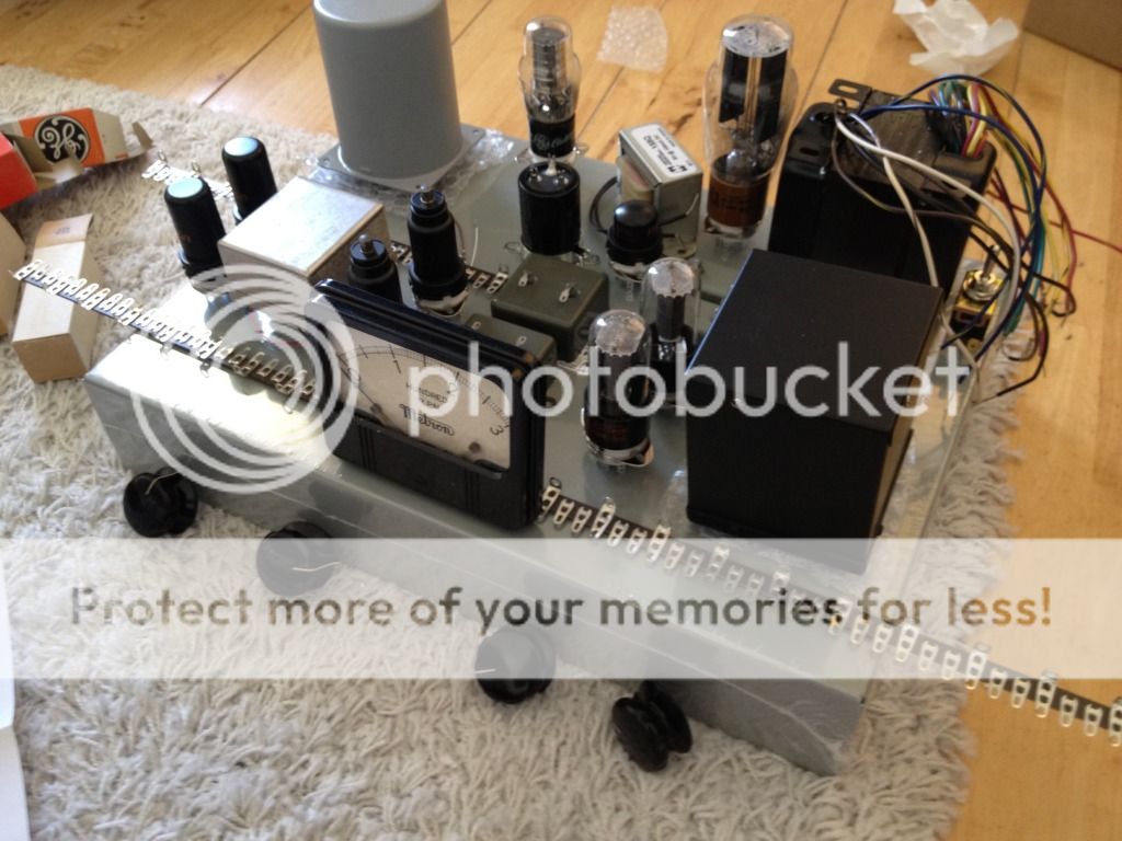
And so it begins!

photo.jpg


This is me playing about with the layout now that I've got the proper enclosure.  The big Russian caps and going to be mounted vertically underneath to save space. I'll also be mounting the choke and obviously the tag strips underneath too.

I've spent a while planning the basic layout, but there's only so much you can do before you start soldering.  The plan is to try and get as many tags in there as possible, so that I have room to change the layout as inevitable oversights emerge!

Oh yes, and that white paper in the top right is a wrapper that one of the PIO caps came in, not a dirty tissue as it may appear to be!

If anyone can see anything glaringly wrong with this layout speak now or forever hold your peace!
 
Dave,  over on your thread you said to calculate the wattage rating of the two balance pots I should take a look at the voltages on your schematic and use Ohm's law.  I've attached your schematic for reference.

For the Balance A pot, I get .2916W (given the values of 5.4V and 100r), but wouldn't the amount of watts dissipated increase as the resistance of the pot lessens when you turn it?  (I have a feeling this is an electronics 101 question that I should know already!)


I'm not sure how to work out the watts across the Balance B pot.  How do I work out the volts across the pot?

Apologies for the stupid questions!

I also have a question about the 1uf coupling caps between the 6J7s and the 6V6s.  How closely do they need to be matched.  I just tested my two PIO caps and one came up as .9uf while the other was .4uf.  Is this going to be a problem, do you think?  The tolerances in tube circuits are pretty wide aren't they?  Or is this too much?
 

Attachments

  • dq2ob6.jpg
    dq2ob6.jpg
    101.4 KB
I finally finished drilling the many holes in the case (picture attached).  Didn't realise there were so many to drill!

The 6SK7 tubes require 6.3VDC on their heaters.  According to the 6SK7 data sheet, each tube needs .3A of current. 

Instead of using the RCA schematic, I used this circuit with a toroidal transformer that's separate from the main Hammond PT.  Here is a synopsis of the set up:

Power TX 2x 6V secondaries 30VA -> bridge rectifier using 4x 1N5402 diodes (these can handle 3A) -> 4700uf smoothing cap -> a simple LM317 circuit from the LM317 data sheet -> the two 6SK7 tubes.

I should be able to get a maximum of 1.5A from the output of the LM317 @ 6.3VDC.

The plan is to heatsink the LM317 to the metal case of the unit (isolating the tab, of course).

In the meantime, I thought I would try and hook it up to see if my stripboard layout worked.  It did.  I was able to dial in 6.3VDC with the LM317 no problem.  I plugged in the first 6SK7 and that too seemed fine (although my multimeter measured 6.15VDC).  When I plugged in the second 6SK7, the voltage dropped rapidly to nothing.  The LM317 had obviously gone into thermal shutdown, and touching it after I had shut off the power confirmed it: I got a nasty burn when touching the tab on the regulator.

As I was just testing the circuit to see if it worked, I hadn't heatsinked the regulator, but I was still surprised that it shut down so quickly, when the tubes were only drawing .6A.  Is this normal and to be expected?

I measured the DC before the regulator and it was about 18VDC.  That is a lot of volts to dissipate.  Is this too much, do you think?
 

Attachments

  • BA6A-CaseWEB.jpg
    BA6A-CaseWEB.jpg
    456 KB
So I've got an insulator/ isolator for the LM317 now and everything works fine now it's heatsinked to the case.  I can dial in 6.3VDC with both 6SK7 tubes plugged in.

The bolt that attaches the regulator to the case does get very hot still (although apparently not enough to cause thermal shut down).  Do you think it's worth getting a smaller transformer?  At the moment I'm using a 2x 6V 30VA toroidal, perhaps I should downsize...?

Thanks!
 

Latest posts

Back
Top