Poor Man's Pultec EQP1-A Build Support Thread

GroupDIY Audio Forum

Help Support GroupDIY Audio Forum:

This site may earn a commission from merchant affiliate links, including eBay, Amazon, and others.
I've just paid. ;D

But i have questions.

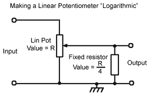
What will happen if i use all pots linear? Cause there is no log pot in here. I know i will get different values with linear pots.Is there anyone use all pots linear?

Or can convert like this?

lin_to_log_pot.gif


Thanks.
 
If you use a linear pot instead of a log pot then the response is likely to be cramped towards one end of the scale. The law of the pots in an EQ is a compromise anyway because you do not want an exactly log or exactly linear response. Slugging a linear pot with a resistor does not work in an EQ because it makes the maximum value wrong. If I were you I would just try linear pots throughout and see what you get.

Cheers

Ian
 
ruffrecords said:
If you use a linear pot instead of a log pot then the response is likely to be cramped towards one end of the scale. The law of the pots in an EQ is a compromise anyway because you do not want an exactly log or exactly linear response. Slugging a linear pot with a resistor does not work in an EQ because it makes the maximum value wrong. If I were you I would just try linear pots throughout and see what you get.

Cheers

Ian

Thanks Ian.

I will try with breadboard when i wait pcbs.

EDIT

I tried with linear pot.Now i'm looking for log-pot. :mad:
 
Ok, I've finally got mine put together and fired up.  Let the troubleshooting begin!  :)  The good news is that all four (I built 2 stereo units) have the exact same behavior, so I'm pretty sure I misread some diagrams or something.

The symptoms are a) no signal in eq bypass mode, and b) no mid control at all.

I've got some suspicions about where I went wrong, so maybe someone can answer a couple of questions for me.  Thanks in advance for any help.

1)  Should the shield on the Pout cable (connected to "PG") be connected to ground, or cut and left unconnected at the switch end?  I did the latter.  If that's correct, then why else might I have zero signal in bypass mode?

2)  I've got pin "G" on the mid board going to both the low boost pot and pin 5 of Chrion's inductor.  I've also got the middle terminal of the mid boost/cut switch going to "screen" on the mid board, which as far as I can tell only connects to the metal brackets on the inductor.  Is this possibly because Dave's mid board hookup diagram was intended to be used for Carnhill inductors in conjunction with Ian's fix pdf?  If I've got it wrong, where should wires be connected?

Thanks guys.  Almost there.
 
Hi John,

Pout cable screen should be left unconnected at the switch end. have you fitted the pad components on the PMTGMU PCB? If you have where is the setting of the 1K lin preset pot?

I think you are right about Dave's hook up diagram. If you are using CHrion inductors the 'screen'  pin on the PCB goes to 0V (which is the left hand tag of the low boost pot looking from behind), the 'pot' pin goes to the pot and the 'Ind' pin goes to the boost/off/cut switch.

Cheers

Ian
 
ruffrecords said:
have you fitted the pad components on the PMTGMU PCB? If you have where is the setting of the 1K lin preset pot?

That was the first thing I thought of, but alas, it's at its mid-point.  Rotating it to its full extent in both directions had no effect.

I think you are right about Dave's hook up diagram. If you are using CHrion inductors the 'screen'  pin on the PCB goes to 0V (which is the left hand tag of the low boost pot looking from behind), the 'pot' pin goes to the pot and the 'Ind' pin goes to the boost/off/cut switch.

Thanks.  I'll make the changes and report back.
 
Ok, the mid is fixed and sounds great!  Thanks for the tips, Ian.  Still not getting anything in bypass mode and everything seems to be hooked up according to the schematic. 

I've also noticed now that low boost does not work, but low cut is really pronounced.  I'll noodle around with that and make sure I didn't overlook something.

Once I get everything functioning, I'll hook it up to some sort of analyzer software and see what kind of curves I'm getting, make sure I don't have any dead positions on the stepped attenuators.  I assume there is a software that is every DIYers favorite for that sort of thing?
 
JohnWatkins said:
Spoke too soon.  Mid "boost" works great.  I've got no response on Mid "cut".  :-[
Sounds like the same problem I was having with the trimmers in the wrong spots. Double check you trimmer placements.

Edit: I'd double check your wiring on your bypass switch as well.
 
JohnWatkins said:
Ok, the mid is fixed and sounds great!  Thanks for the tips, Ian.  Still not getting anything in bypass mode and everything seems to be hooked up according to the schematic. 

I've also noticed now that low boost does not work, but low cut is really pronounced.  I'll noodle around with that and make sure I didn't overlook something.

Pronounced low cut and no mid cut is symptomatic of loading the EQ output with too low an impedance - maybe you have the wrong value for the 470K preset on the PMTGMU?

Cheers

Ian
 
Thanks, guys.  I've double-checked all of the wiring against Dave's diagram and the schematic and it seems correct.  I'll check the pots on the tube makeup.  I don't suppose I can measure the values without pulling them, can I?
 
Yep, sure enough;  VR1 and VR2 are in each other's spots.  I think I must have glanced at the part list and assumed that the first one was VR1, when in fact VR2 is listed first.  That'll teach me to be in a hurry.  Re-working them all now.  Hopefully this fixes everything.
 
Yes, that's what I did. I was so confused on the inductors and switches I didn't think to look at these trimmers. Glad you found it.
 
Still having some issues and now going back to square one to understand the theory.  Asking "where do I put this wire" isn't helping me learn or get this thing working.

Please bear with me, as this is all new to me;

As I (barely) understand it, on the mid pcb, "inductor" is meant to be the input to the pin 0 of the inductor from either the bass boost or treble boost pot depending on the switch position.  Then the inductor feeds varying levels of inductance and subsequently varying levels of capacitance through the switch depending on it's position to the "pot" terminal which is meant to go to the center of the mid boost/cut potentiometer?  That then feeds the side of the treble boost pot opposite the side that fed the mid boost switch?

What is the 'screen' terminal's job.  Anything other than just a literal screen for hum cancelling?

Thanks for your help and patience.
 
@John

The EQ is basically a pot divider consisting of the treble boost pot (47K) and the treble cut pot (4K7) giving a nominal 20dB loss. (Ignore the bas boost pot for now and assume it is off i.e. short circuited. Boost is achieved by frequency selectively shorting out the treble boost pot. For the mid boost that is done by connecting the pot L, C and and R in series across it.

Cut is achieved by frequency selectively shorting out the treble pot. Changing the mid switch does this by connecting one end of the RLC to ground.  Hopefully this is clear if you look at this schematic.

http://www.ianbell.ukfsn.org/EzTubeMixer/docs/PMEQP1A/PMEQMIDv1.1.png

The 'screen' connection is there to allow the metal clasp that holds the inductor together to be connected to 0V.

Cheers

Ian
 
So with the treble boost pot fully counter-clockwise (off) the resistance is equal across all frequencies, but the makeup amp is providing gain equal to that resistance, so nothing happens, and when you turn it up you're providing a path of less/least resistance for the signal at whatever frequency the switch is set to?
 
JohnWatkins said:
So with the treble boost pot fully counter-clockwise (off) the resistance is equal across all frequencies, but the makeup amp is providing gain equal to that resistance, so nothing happens, and when you turn it up you're providing a path of less/least resistance for the signal at whatever frequency the switch is set to?

Exactly. All passive EQ works in the same way; some of them are just drawn so badly it is impossible to see it but the bottom line is you can redraw them all to look like this.

Cheers

Ian
 
Eureka!  Several bone-headed mistakes fixed, and I now have bass boost.  The only problem that now remains is with the mids.  I have no cut control.  Everything else works perfectly at this point.  Any ideas as to what would cause the boost to function, but not the cut?  Thanks again.
 
Back
Top