Poor Man's Pultec EQP1-A Build Support Thread

GroupDIY Audio Forum

Help Support GroupDIY Audio Forum:

This site may earn a commission from merchant affiliate links, including eBay, Amazon, and others.
ruffrecords said:
Yes, all the PSU caps are electrolytic.  In all cases the - leg is connected to 0V. The 220uF from the cathode of the bottom triode to ground is also electrolytic - it should be 50V working type or better.

The 4.7uF from the top triode cathode to the transformer is NOT an electrolytic. It should be a 450V working metal film type.

Cheers

Ian

I understand you mean the two 2u2 caps in the Make up gain Pcb? I got a pair of 250v, should I change them?
 
dirtyhanfri said:
I understand you mean the two 2u2 caps in the Make up gain Pcb? I got a pair of 250v, should I change them?

That is correct. They really do need to be 400V working so I recommend you change them.

Cheers

Ian
 
ilfungo said:
Sorry where i can find the right  pot in Europe? (4k7 - 47k log - 470k log)
Thanks
Hi, here in germany it´s easy,e.g. Reichelt.
Look here:

http://www.reichelt.de/?ACTION=2;GROUPID=3135;SHOW=1;SID=11TfPHtH8AAAIAAFsZIxsee1eadf0815ceb8aecd183fa1d3eebfd

Best regards,

Udo.
 
I just got my first face and rear pannels, designed by me, cutted & drilled by my homie Baresi (Thanks man)

Now I´m dealing with stepped switches...

It´ s too bad to connect resistors in series to get the right value?

I should solder the 12 switch pins to a leg of a resistor, and the other end?

I´ve been looking around and didn´t found anything clear.

Thanks.
 
Pics of the pannels

29072011459.jpg


29072011460.jpg


29072011461.jpg


Waiting for black paint and white lettering
 
dirtyhanfri said:
Now I´m dealing with stepped switches...

It´ s too bad to connect resistors in series to get the right value?

I should solder the 12 switch pins to a leg of a resistor, and the other end?

It is OK to connect resistors in series to get the right value.

It is common practice to wire the resistors directly to switch pins.

Cheers

Ian
 
dirtyhanfri said:
And the other side of the resistors?

I am not sure what you mean. For a stepped resistor switch you would normally wire the resistors across adjacent pins on the switch. You calculate the resistor values such that the sum from the start position is the required value at each switch position.

Cheers

Ian
 
ruffrecords said:
dirtyhanfri said:
And the other side of the resistors?

I am not sure what you mean. For a stepped resistor switch you would normally wire the resistors across adjacent pins on the switch. You calculate the resistor values such that the sum from the start position is the required value at each switch position.

Cheers

Ian

Ok thanks, I´m gonna make some research about this.
 
Ok, I think I got it...


I have to solder the 12 resistors across the pins, and then (as I can understand looking at the "hookupsm.jpg" you posted at the top of the topic) I have to wire T1 to Pin 12, T2 to Pin "A" in the High Boost Switch, right? (If I`m ok with this I understand the other switches)

And, for linear stepped switches; maybe it`s obvious, but I`d like to be sure, Total R / Nº of steps - 1

For 4K7 with 12 steps It should be 4700 / 11 = 427,27

Is it ok? or I`m wrong?

Thanks, and sorry my poor english, its frustrating when don`t know how to say exactly what you want to say.
 
dirtyhanfri said:
Ok, I think I got it...


I have to solder the 12 resistors across the pins, and then (as I can understand looking at the "hookupsm.jpg" you posted at the top of the topic) I have to wire T1 to Pin 12, T2 to Pin "A" in the High Boost Switch, right? (If I`m ok with this I understand the other switches)

That seems about right. The pin A on the switch resistor is the wiper of the pot. I think pin1 of the switch will be the anti-clockwise position of the switch resistor so T1 would go to pin 1 and T2 to pin A for the Hi boost.

And, for linear stepped switches; maybe it`s obvious, but I`d like to be sure, Total R / Nº of steps - 1

For 4K7 with 12 steps It should be 4700 / 11 = 427,27

Is it ok? or I`m wrong?

OK. 12 steps means 11 resistors so each is R/11. how to say exactly what you want to say.

And your English is very good!

Cheers

Ian
 
Ok, Thanks

Fisrt of all, a pic of almost everything soldered (only the linear stepped switches left)

01082011463.jpg


Now a pair of questions...

The Psu could be enough to feed a 2 channel version?

What about the heaters? I just left this for the end because I have no idea what is this about, something like this?

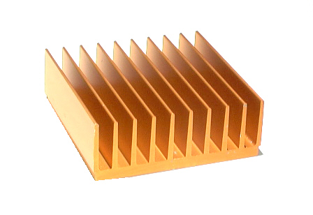
disipador-calor.jpg


Thanks, you`re great ruffrecords!
 
dirtyhanfri said:
Now a pair of questions...

The Psu could be enough to feed a 2 channel version?

What about the heaters? I just left this for the end because I have no idea what is this about, something like this?

Yes the PSU will feed two channels provided you use a mains transformer with enough current capability.

As others have said, the heaters are in the tubes themselves. They are what glows red. They need a 6.3V ac supply at 0.6amps each if you use the 6CG7 tube. You can normally obtain a single transformer with separate 6.3V ac and HT windings.

If this is your first ever tube [project then please be very careful. Very high voltages are involved and the tubes themselves get very hot.

Cheers

Ian
 
Thanks for the advice

Of course I´m being as carefull as I can, and I´m specially worried about the power supply (I understand basics of electricity and know where don´t touch). I just soldered the power supply comps to a perfored board and wired point  to point. I wont make it run untill I´m totally sure, I don´t want to die in my first project ;)

Thanks again for the advice, and don´t worry, I ´ ll be careful.
 
Hi, I think It`s time to think in the wiring while waiting for the tube and a pair of caps.

Many doubts...

-In the make up gain stage schematic;  HT+ in the Power Supply HT goes to HT in the gain stage PCB? In the Schematic too, "TO HEATERS" Goes to H1 & H2 in The gain stage Pcb? If It`s ok, where should I connect the "6.3 V AC" points of the Schematic?

-P In & P Out in the Gain Stage Pcb are for the Pad circuit? I`d like to get over the whole circuit (Gain stage included) with the "EQ In-Out" Switch, like a Bypass, should I install any jumper?

-In & IG in the Gain Stage Pcb are for the Input?

-PG Is for 0V? Chassis?

-** Point in the Gain Stage Pcb is wired to chassis?

-If I`m gonna use unbalanced inputs and outputs, ¿I need to use transformers?


Maybe If I`m totally wrong about this…

Thanks
 
dirtyhanfri said:
Hi, I think It`s time to think in the wiring while waiting for the tube and a pair of caps.

Many doubts...

-In the make up gain stage schematic;  HT+ in the Power Supply HT goes to HT in the gain stage PCB? In the Schematic too, "TO HEATERS" Goes to H1 & H2 in The gain stage Pcb?

Yes and yes.

If It`s ok, where should I connect the "6.3 V AC" points of the Schematic?

That needs to come from the mains transformer secondary.

-P In & P Out in the Gain Stage Pcb are for the Pad circuit?

Yes.

I`d like to get over the whole circuit (Gain stage included) with the "EQ In-Out" Switch, like a Bypass, should I install any jumper?

I am not sure what you mean here. Do you want an EQ in/out switch?

-In & IG in the Gain Stage Pcb are for the Input?

-PG Is for 0V? Chassis?

-** Point in the Gain Stage Pcb is wired to chassis?

I have noticed some inconsistencies between the system diagram, the gain make up schematic and system diagram. I will draw it all on one sheet of paper to make it clear.

-If I`m gonna use unbalanced inputs and outputs, ¿I need to use transformers?

No, you do not need to use transformers.

Cheers

Ian
 
ruffrecords said:
dirtyhanfri said:
If It`s ok, where should I connect the "6.3 V AC" points of the Schematic?

That needs to come from the mains transformer secondary.


I think I don´t get it, should I geg a toroid transformer with 6.3v ac secondary? Then... 2 power inputs? One for the psu and one for the psu? Surely not.... But I don´t fully understand it.

Thanks for your patience
 
Back
Top