You are using an out of date browser. It may not display this or other websites correctly.
You should upgrade or use an alternative browser.
You should upgrade or use an alternative browser.
Poor Man's Tube Compressor
- Thread starter ruffrecords
- Start date
Help Support GroupDIY Audio Forum:
This site may earn a commission from merchant affiliate
links, including eBay, Amazon, and others.
MeToo2
Well-known member
Interesting.analag said:It may return...with some changes.
Why does the side chain detector filter (indirectly) connect to the cathode resistor of the input tubes, rather than both just referencing straight to ground?
Is that part of a cunning plan?
MeToo2 said:Interesting.analag said:It may return...with some changes.
Why does the side chain detector filter (indirectly) connect to the cathode resistor of the input tubes, rather than both just referencing straight to ground?
Is that part of a cunning plan?
Actually it's not if you look at it closely. What is shared is the voltage source.
MeToo2
Well-known member
Oops. I thought that was a voltmeter to measure GR. :-[analag said:MeToo2 said:Interesting.analag said:It may return...with some changes.
Why does the side chain detector filter (indirectly) connect to the cathode resistor of the input tubes, rather than both just referencing straight to ground?
Is that part of a cunning plan?
Actually it's not if you look at it closely. What is shared is the voltage source.
Now I look again I see it's DC biasing of approx 2.5V + 2.3 * Icathode on the cathode and 12.5V on the grids
=> Vanode-cathode ±90V, Vgrid-cathode -1.5V, and Icathode ±5mA. Is that about right? :
MeToo2 said:Now I look again I see it's DC biasing of approx 2.5V + 2.3 * Icathode on the cathode and 12.5V on the grids
=> Vanode-cathode ±90V, Vgrid-cathode -1.5V, and Icathode ±5mA. Is that about right? :
Vanode-cathode ±117
ruffrecords
Well-known member
It has been a year since the last post on this topic. Despite that I was not completely discouraged and have continued to experiment with Vactrols on occasion. Most recently I have been refurbishing an circa 1940 RCA tube PA amp for a client who asked me also to look into the possibility of using a Vactrol to turn it into a compressor. A little while back I did some simple experiments with this and to my surprise I quite easily converted it into a 4:1 ratio compressor. It is so simple I think you could probably do a compressor with just a couple of tubes. Is there still any interest in this?
Cheers
Ian
Cheers
Ian
Hi Ian, your advice on one of my projects on another thread has been so helpful, many thanks. And yes, I think there is interest for a simple two valves compressor around here. Most of the valve comps I have seen around tend to go into long lists of parts/exotic Xfos and valves of all sorts. Think Gates and others of the same lineage.
A simple two valve compressor? Yes.
A simple two valve compressor? Yes.
rmaier
Well-known member
Yup.
MeToo2
Well-known member
Presumably if you're talking vactrols you're thinking mono? [to avoid the not inconsiderable difficulty of matching any 2 units]ruffrecords said:Most recently I have been refurbishing an circa 1940 RCA tube PA amp for a client who asked me also to look into the possibility of using a Vactrol to turn it into a compressor.
Cheers
Ian
BTW Vactrol are now sold under the brand "Excelitas Tech" if anyone's looking for new parts. But they're not getting any cheaper or easier to buy, presumably because of lack of RoHS compliancy.
ruffrecords
Well-known member
MeToo2 said:Presumably if you're talking vactrols you're thinking mono? [to avoid the not inconsiderable difficulty of matching any 2 units]ruffrecords said:Most recently I have been refurbishing an circa 1940 RCA tube PA amp for a client who asked me also to look into the possibility of using a Vactrol to turn it into a compressor.
Cheers
Ian
Indeed. Matching would be very non trivial.
BTW Vactrol are now sold under the brand "Excelitas Tech" if anyone's looking for new parts. But they're not getting any cheaper or easier to buy, presumably because of lack of RoHS compliancy.
Farnell still seem to have many types in stock except for the VTL5C3 which is very annoying as that is the one the design uses at present..
What is the ROHS issue? Is that with the photocells?
Cheers
Ian
ruffrecords
Well-known member
Well, despite the chosen Vactrol being hard to come by, here is the initial schematic of the two tube compressor. Obviously I need to look at alternative opto devices.

The gain make up stage is one of my mu followers but this time using a 6922 (6DJ8/ECC88). You can add an ouptu transformer if you want a balanced output. The side chain, connected to the wiper of the threshold pot, uses an SRPP for its superior drive capability since distortion is not really an issue. The 1K series resistor gives a threshold at about 1.6 volts at the SRPPm output. The reverse connected LED across the Vactrol operates on the other half cycle and stops the output capacitor just charging up.
I have not built this circuit but I have tested most parts of it. The Vactrol certainly works and gives a compression ratio of around 4:1. The mu follower is also known to work. The only really untested part is the side chain SRPP which I have simulated but not built. I expect to be able to verify this in the next few days.
Cheers
Ian
MeToo2
Well-known member
Yep. VTL5C3 is type 3 material. It's the Cadmium (sulphide or selenide). No real way around it AFAIK. Cadmium is limited to 0.01% or 100 ppm for any single block of material e.g. the LDR material itself not including its encapsulation. But that's precisely what gives the vactrol it's specific response properties (steep slope + good dynamic range + low light memory). Regulation gone mad.ruffrecords said:What is the ROHS issue? Is that with the photocells?
Cheers
Ian
merlin
Well-known member
- Joined
- Aug 17, 2011
- Messages
- 380
If the actual compression is done with an LDR, does it really qualify as a 'tube compressor'? I mean, the tubes are really just being used for clean gain. You could replace them with SS and still get the same compression response... Just sayin...
Anyway, I though I'd post this 1951 article about suppressor-grid compression, in case it interests anyone. The original is intended for a radio receiver of course, but the principle could easily be applied to a studio compressor, with minimal parts.
http://dl.dropbox.com/u/57831278/1951_Suppressor_Compression_AGC_Amos.pdf
As an aside, "variable-mu" is short for "variable mutual conductance" (i.e., variable gm) and does NOT refer to valve constant that we use the Greek letter mu for! This has been a source of confusion since the day it was coined (1940s?), and really was a poor choice of name!
flaheu
Well-known member
thanks, very interesting document.
ruffrecords
Well-known member
merlin said:If the actual compression is done with an LDR, does it really qualify as a 'tube compressor'? I mean, the tubes are really just being used for clean gain. You could replace them with SS and still get the same compression response... Just sayin...
I agree. I looked at lots of tube based 'gain reduction' or ''variable gain' elements but as you will no doubt have seen from the earlier parts of the thread, they all have 'thump' issues which tend to lead to balanced and hence more complex designs. I was aware of the LA2A but the current replacements for its opto cell are very expensive. Then someone mentioned Vactrols and I thought "great!" but of course fairly cheap Vactrol designs abound. Hence the gap of a year before I came up with anything resembling a poor man's compressor.
That said, yes it is not a tube based gain element and yes, you could put cheap op amps around it. Then again, that is all part of the poor man's spirit. Many people have built the poor man's EQP1A with op amps instead of tubes. So in the spirit of a 'poor man' I will rename this thread the poor man's compressor and leave out the tube specific. I guess you could do a fully balanced version with just a pair of NE5532 op amps.
And by the way, thanks for pointing out that article. I have not seen that one.
Cheers
Ian
MeToo2
Well-known member
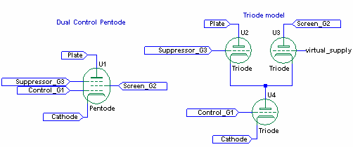
I couldn't get my head around this. An article from Radiomusem with equivalent triode model seemed to make more sense to me at least in understanding how it worked.merlin said:Anyway, I though I'd post this 1951 article about suppressor-grid compression, in case it interests anyone. The original is intended for a radio receiver of course, but the principle could easily be applied to a studio compressor, with minimal parts.
http://dl.dropbox.com/u/57831278/1951_Suppressor_Compression_AGC_Amos.pdf

mjk
Well-known member
Interesting. The tube would need to have enough screen grid dissipation capability relative to the plate. It might be fun to wire up a suitable pentode and play with it. I'm assuming true pentodes and not beam tetrodes...
MeToo2
Well-known member
I don't claim any special knowledge (this is all new to me) but the radiomuseum article I linked to listed a bunch of pentodes suitable for dual control. It included the good ol' PF86 of which I already have a bunch. [5V heater version of EF86]mjk said:Interesting. The tube would need to have enough screen grid dissipation capability relative to the plate. It might be fun to wire up a suitable pentode and play with it. I'm assuming true pentodes and not beam tetrodes...
what is the effect of the inherent turn on and turn off response of the vactrol? With a 35mS release time, wouldn't it be generating significant distortion at low frequencies? Do you really want such a fast release? The opto cells in a LA2A had a much slower release or turn off time and indeed were hand graded to pick the few from any one batch that met the characteristcs required.
Similar threads
- Replies
- 2
- Views
- 1K


