Preamp difference : if it's not the frequency, not the slew rate, and not the harmonics, what is it ?

GroupDIY Audio Forum

Help Support GroupDIY Audio Forum:

This site may earn a commission from merchant affiliate links, including eBay, Amazon, and others.
Ian, I believe it was you...perhaps someone else?....that had documented results of A/D convertors having a "hard coded" roll-off at 20K-ish regardless of the sampling rate. Or am I imagining something? Thanks for any clarification....

Bri
Some convertors have band pass or low pass filters built in... read the data sheets.

JR
 
I was talking about processing inside the DAW not the sound of converters at different sample rates. If you are mixing ITB the processing power has to be up to the task.

The Prism AD2 I use sounds pretty much the same at all sample rates. That’s about a 30 year old design. Some converters do sound noticeably different at different sample rates.
I had a Prism Dream and I agree it is a fantastic converter. Only 2 channels, so I replaced it long ago, but I made great records (mostly 48 kHz) with it.
 
Some convertors have band pass or low pass filters built in... read the data sheets.

JR
IIRC, Ian or someone else discovered that some commercial ADs "hid the fact" the bandpass was hard-coded to 20 kHz, regardless of sampling frequency. That fact was not divulged in the spec sheet.

But maybe I'm mistaken....

Bri

/EDIT when searching the internet on this topic, I see hundreds of sites comparing the "sonics" of convertors. "Model X sounds a bit nasally in the 3.65879 kHz region". "Model Y lacked soundstage width in the upper midrange."

Old School...poke a test generator in and plot the results! <g>
 
Last edited:
IIRC, Ian or someone else discovered that some commercial ADs "hid the fact" the bandpass was hard-coded to 20 kHz, regardless of sampling frequency. That fact was not divulged in the spec sheet.

But maybe I'm mistaken....

Bri

/EDIT when searching the internet on this topic, I see hundreds of sites comparing the "sonics" of convertors. "Model X sounds a bit nasally in the 3.65879 kHz region". "Model Y lacked soundstage width in the upper midrange."

Old School...poke a test generator in and plot the results! <g>
A whole swag of different types of filters exist, or have existed in the past, on A/D & D/A converters, some are set to follow the sample rate, some are set to roll off at around 20KHz, some have Smooth/Slow filters (which start rolloff around 10K dropping to 20K if using 44.1) and some have Sharp/Fast filters that drop like a stone, there’s Linear Phase, Minimum Phase, Short Delay/Sharp Rolloff, Short Delay/Slow Rolloff, Super Slow Rolloff, Low Dispersion/Short Delay - all have their own curves and quirks
 
except...


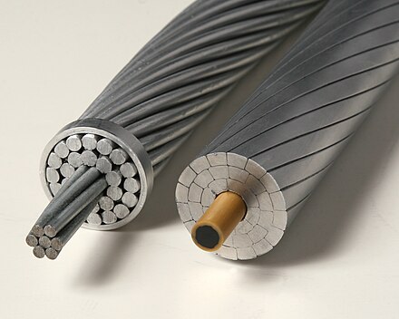
Wires used for utility power distribution often used steel cores for strength, with aluminum conductors wrapped around that core for lower resistance. The higher resistance steel core doesn't matter as much because due to skin effect most of the current is flowing in the aluminum.

JR

,

Given skin effect’s (loosely) an exponential function of frequency, while I'd never argue there's zero effect at 50/60Hz power transmission frequencies, the attributable loss is insignificant ... even when you consider the very long distances in the business of power distribution when the very small incremental loss per foot due to skin effect may become noticeable over hundreds of miles but remains negligible compared to other losses; it is, quite literally, below the noise floor. Did Wiki offer a citation to support this point, beyond vague references to the original papers by Lamb and Heaviside which are not specific to LF power distribution?


Just fyi, I've discussed this at length with a lecturer in HV electricity whose PhD was gained in power distribution. I can't quote him verbatim to avoid his colourful language but in essence, skin effect's there but ... it's ‘one bug on a large windshield'. The use of HVDC for long distance transmission is more to do with avoiding reactance in cables plus the requirement to interface disparate, unsync'd national power systems, than because of skin effect ... the fact DC distribution avoids skin effect is a nice to have side-benefit, rather than the main driving reason.

The use of steel / aluminium composite cables is fundamentally to make use of the tensile strength of steel (which forms the central "strainer") while maximising transmission capability using aluminium’s great conductivity and low weight. But wouldn't the fact most current flows in the aluminium outer strands simply relate to aluminium having significantly higher - about 20 times greater - electrical conductivity than steel? Specifically, compared to copper (assuming copper gives us 100% benchmark) then aluminium is just over 60% whereas steel is around 3% to 4%.
 
Yes - but seeing as how all DUTs are getting the same distortion then the difference between the DUTs will be a measure of their own distortion of the distortion
Each DUT has its own non-linearity, which may well react differently to any artifacts in the aource A-D. These become like a multi-tone distortion stimulus, which different results among the DUTs. Best to have the cleanest possible input?
 
Each DUT has its own non-linearity, which may well react differently to any artifacts in the aource A-D. These become like a multi-tone distortion stimulus, which different results among the DUTs. Best to have the cleanest possible input?

Very true. In my opinion, design should be about minimising the number of stages placed in the signal path rather than adding buffers here, there and everywhere without good reason.
 
For an old rule of science....


Of course most modern A/D convertors over-sample so don't lose too much sleep on the details.

JR

Quite! Sample rate (per Nyquist et al.) firmly limits the highest frequencies any analogue-to-digital or digital-to-analogue conversion can cope with but increasing it doesn't necessarily mean greater bandwidth because the HF limit is affected by many more things.

Frankly, one of the main reasons to deliberately limit frequencies over about 20kHz is more to avoid instability rather than throwing away anything of value.
 
IIRC, Ian or someone else discovered that some commercial ADs "hid the fact" the bandpass was hard-coded to 20 kHz, regardless of sampling frequency. That fact was not divulged in the spec sheet.

But maybe I'm mistaken....

Bri

/EDIT when searching the internet on this topic, I see hundreds of sites comparing the "sonics" of convertors. "Model X sounds a bit nasally in the 3.65879 kHz region". "Model Y lacked soundstage width in the upper midrange."

Old School...poke a test generator in and plot the results! <g>
Oversampled A/D convertors use decimation or downsampling filters. These filters can deliver different bandpasses by design. I repeat read the specific convertor data sheet.

The WWW is full of audio claims with differing veracity.

JR
 
Maybe you missed the "HD" part?
24bit 192kHz, 352.8 KHz.
yeah, let's not confuse the Nyquist theorem.
If those sample rates are from masters, and not just upsampled from 44.1/16 it could be good.

Sample rate, discussed extensively elsewhere, has little to do with the number of bits used in a digital representation. So what is the difference between 16-bit v's 24-bit for example? Fundamentally, it's the audio signal level where the quantisation noise becomes apparent / measurable / obtrusive. In theory, the greater the number of bits, the wider the dynamic range which can be captured ... and hence the quieter signals can be recorded with less quantisation noise. In most practical applications, once you go much past 16-bit, the quantisation noise is is close enough to the noise floor to be immaterial. This could be why the sound guy was dismissive of the real life benefits of 24-bit over 16-bit.
 
I take issue with 'Quantisation Noise', no such thing, in an improperly dithered (Which is to say broken!) quantiser you get quantisation distortion not noise (Distortion is correlated with the signal, noise is uncorrelated), and in a correctly dithered quantiser you get a constant noise floor at about 1LSB which is independent of the applied signal and sets the noise floor.

There are two things, sample rate, which sets the maximum possible bandwidth that can be unambiguously captured, and word length which sets the best case noise floor (And hence dynamic range).

It is however possible to make some tradeoffs here, every time you decimate by 2 you gain an extra 3dB of SNR (Providing the quantiser is correctly dithered), and most modern ADCs leverage this hard, typically being at core a 1 bit DSM of reasonably high order going at MHz rates that then gets decimated down to the output rate within the digital side of the converter chip. This has the really nice advantage that a simple second order lowpass at about 60kHz (Plus the usual RFI networks and such) is entirely sufficient to avoid aliasing, when the DSM is going at 6MHz energy just above the audio band is a non issue irrespective of final output rate as long as the decimating filters are right. Usually you get about 20 bits effective with good modern ADC sand, the rest are just noise.

One nice trap is that many ADCs use half band filtering in the decimators, which saves a lot of multipliers in the IIR, has a good stopband performance, but is only -6dB at the half band point! This means that there is a small region just below output Fs/2 where energy present at just above Fs/2 can alias and appear in the output. It is typically only a kHz or so wide, and not exactly where most humans have much hearing but it is there.

The answer of course is to follow the ADC with a digital filter designed to roll off before this energy appears, slightly annoying to write for a 44.1 or 48k chain as you are working painfully close to Fs/2, but it can be done.

I would note that the critical clock is the modulator clock at typically 24.576MHz or so (Likely divided down internally to somewhere in the 6 or 12MHz region), as it it this that sets the actual conversion timing, it has also mostly not been an issue in about 20 years, but once very much was.

On the subject of preamps I am suspicious that overload behaviour and recovery might be a fertile place to look, not like we all use the API rack for drums because we don't expect it to clip....

16 bits as a distribution format is at least mostly fine, but it is something of a pain in a production context, you have to be all together too careful with gain structure to avoid the noise becoming audible. A GOOD analogue frontend chain manages about 120dB of dynamic range, which happens to match what a real 24 bit converter will typically do quite nicely, that extra 20 odd dB makes a real difference in takes lost to underestimating the tubes on the singer....

Erm, it's broadly "potayto potarto".

AFAIK quantisation "noise" is generally accepted, with Signal to Quantisation Noise (SQNR) being the recognised term.
 
Given skin effect’s (loosely) an exponential function of frequency, while I'd never argue there's zero effect at 50/60Hz power transmission frequencies, the attributable loss is insignificant ... even when you consider the very long distances in the business of power distribution when the very small incremental loss per foot due to skin effect may become noticeable over hundreds of miles but remains negligible compared to other losses; it is, quite literally, below the noise floor. Did Wiki offer a citation to support this point, beyond vague references to the original papers by Lamb and Heaviside which are not specific to LF power distribution?


Just fyi, I've discussed this at length with a lecturer in HV electricity whose PhD was gained in power distribution. I can't quote him verbatim to avoid his colourful language but in essence, skin effect's there but ... it's ‘one bug on a large windshield'. The use of HVDC for long distance transmission is more to do with avoiding reactance in cables plus the requirement to interface disparate, unsync'd national power systems, than because of skin effect ... the fact DC distribution avoids skin effect is a nice to have side-benefit, rather than the main driving reason.

The use of steel / aluminium composite cables is fundamentally to make use of the tensile strength of steel (which forms the central "strainer") while maximising transmission capability using aluminium’s great conductivity and low weight. But wouldn't the fact most current flows in the aluminium outer strands simply relate to aluminium having significantly higher - about 20 times greater - electrical conductivity than steel? Specifically, compared to copper (assuming copper gives us 100% benchmark) then aluminium is just over 60% whereas steel is around 3% to 4%.
Skin effect is not the dominant reason for steel core utility cables....strength is, but skin effect is a little serendipitous icing on the cake that makes the conduction losses from the strength core innocuous.
wiki said:
At 60 Hz in copper, skin depth is about 8.5 mm. At high frequencies, skin depth becomes much smaller.

While the skin depth might be a little different for steel/aluminum, big dog high voltage mains frequency cables could be fat enough for a 1/3" skin effect to crowd most conduction into the outer more conductive aluminum wrap.

modern power lines use carbon fiber core for strength/weight benefits.
440px-ACSR_and_ACCC.JPG


JR
 
Skin effect is not the dominant reason for steel core utility cables....strength is, but skin effect is a little serendipitous icing on the cake that makes the conduction losses from the strength core innocuous.


While the skin depth might be a little different for steel/aluminum, big dog high voltage mains frequency cables could be fat enough for a 1/3" skin effect to crowd most conduction into the outer more conductive aluminum wrap.

modern power lines use carbon fiber core for strength/weight benefits.
440px-ACSR_and_ACCC.JPG


JR
Point is John, we're saying the same thing! If at 60Hz the skin depth is 8.5mm, i.e. 17mm (or 2/3") diameter, then seriously, no ... really seriously ... that's way, way thicker than any cables in my system. And I'll stake my life it's more than ANY cable in any rock band's PA rig. Imagine the weight, never mind the cost. [Listen to the sustain ... Ah .. ] And I take your point (and the formula) that the skin depth rapidly decreases at higher frequencies but even so, it's a lot of meat to eat before I run out of even speaker cables where I tend to use Van Damme 2.5 or 4.0mm sq (which are around 1.8mm and 2.3mm diameter respectively). So to go back to my original postulation: I don't think skin effect is really an issue at audio frequencies.

It's a long, long time since I looked at the piece of cable from the overhead line (we were shown it on a school trip when I was about 5 or 6 year old)! And stuff might've moved on since but having asked t'internet, a very quick n dirty answer feels like 3" to 4" diameter bundles like the ones on your pic above. What's less clear to me is whether the skin effect applies separately to each "strand" (in which case 8.5mm 'skin' could well be all of the conductors) or whether the bundle is treated as a whole (in which case the same 8.5mm skin would be like a coat of paint on the handrail ....!)

Cheers, Will
 
I take issue with 'Quantisation Noise', no such thing, in an improperly dithered (Which is to say broken!) quantiser you get quantisation distortion not noise (Distortion is correlated with the signal, noise is uncorrelated), and in a correctly dithered ...

Terminology is never rigidly fixed here. In general terms noise may be correlated or uncorrelated with respect to any signal involved in a system.
 
Point is John, we're saying the same thing! If at 60Hz the skin depth is 8.5mm, i.e. 17mm (or 2/3") diameter, then seriously, no ... really seriously ... that's way, way thicker than any cables in my system. And I'll stake my life it's more than ANY cable in any rock band's PA rig. Imagine the weight, never mind the cost. [Listen to the sustain ... Ah .. ] And I take your point (and the formula) that the skin depth rapidly decreases at higher frequencies but even so, it's a lot of meat to eat before I run out of even speaker cables where I tend to use Van Damme 2.5 or 4.0mm sq (which are around 1.8mm and 2.3mm diameter respectively). So to go back to my original postulation: I don't think skin effect is really an issue at audio frequencies.

It's a long, long time since I looked at the piece of cable from the overhead line (we were shown it on a school trip when I was about 5 or 6 year old)! And stuff might've moved on since but having asked t'internet, a very quick n dirty answer feels like 3" to 4" diameter bundles like the ones on your pic above. What's less clear to me is whether the skin effect applies separately to each "strand" (in which case 8.5mm 'skin' could well be all of the conductors) or whether the bundle is treated as a whole (in which case the same 8.5mm skin would be like a coat of paint on the handrail ....!)

Cheers, Will
I suspect you will find answers to your specific questions by searching the design of litz wire cables for RF use.
===
In case I was not clear "skin effect" has been a very old faux-feature promoted in audiophool circles. Without repeating the entire history "Litz wire" has some application at RF frequencies, for audio not so much. 🤔

Marketers like to use some actual physical phenomenon (like skin effect) and hyperbolically extrapolate that into some selling proposition for funny speaker wire, or funny audio cables. There is lots of money to be made by making up differences where none or very little exist.

I am old and tired so after decades of pushing back against such "audio mythology" I tend to use shorthand and skip ahead to the punchline. The actual skin effect phenomenon in mains power lines (because of the relatively large diameter conductors) is amusing to mention because it creates cognitive dissonance in the minds of local experts who are are convinced there is absolutely nothing going on at 50-60Hz . ;)

JR
 
I suspect you will find answers to your specific questions by searching the design of litz wire cables for RF use.
===
In case I was not clear "skin effect" has been a very old faux-feature promoted in audiophool circles. Without repeating the entire history "Litz wire" has some application at RF frequencies, for audio not so much.

apart from being ever so flexible and unlikely to break ..

Marketers like to use some actual physical phenomenon (like skin effect) and hyperbolically extrapolate that into some selling proposition for funny speaker wire, or funny audio cables. There is lots of money to be made by making up differences where none or very little exist.

Ha! Yup.

I am old and tired so after decades of pushing back against such "audio mythology" I tend to use shorthand and skip ahead to the punchline. The actual skin effect phenomenon in mains power lines (because of the relatively large diameter conductors) is amusing to mention because it creates cognitive dissonance in the minds of local experts who are are convinced there is absolutely nothing going on at 50-60Hz .

Ouch! Erm, fair cop guv. In my defence, I live with 50Hz (obviously infinitely superior, blah blah what ho blah!!) 😂
 
@JohnRoberts serious question: in Litz wire, are the strands insulated from each other? Given it's a pain to solder I think they are, so for skin purposes, each conductor must be considered separately. In power dist. however, I'm sure the separate 'hawsers' aren't insulated from each other ... and I'm heading back to my coat of varnish on a handrail analogy. But in any case, this is a 'heck' of a long way from the OP, isn't it?
 
Last edited:
@JohnRoberts serious question: in Litz wire, are the strands insulated from each other? Given it's a pain to solder, I think they are so for skin purposes, each conductor can be considered separately. In power dist., I'm sure the separate 'hawsers' aren't insulated and I'm heading back to my coat of varnish on a handrail analogy. But in any case, this is a 'heck' of a long way from the OP, isn't it?
I suspect they are coated to keep the center of conduction in the middle of each fine strand, otherwise they would behave like thicker wires forfeiting some of the higher relative conductive surface area benefit.

But like I suggested a quick search will reveal lots of "litz" specific information.

FWIW I have never used Litz wire and don't plan to.

JR
 
Proper Litz has each strand insulated, and a cable lay up such that each strand moves from the centre to the outside and back over the length, thus reducing the effective length over which skin effect applies.

It does NOT contrary to popular belief eliminate skin effect, but does (in the correct application) markedly reduce copper losses and (in tuned circuits in the 100kHz to a few MHz) usefully raise the Q.

The place you tend to see it these days is in SMPSU transformers, induction hobs and wireless chargers.

Incidentally, there IS a version used in grid scale transmission systems, the "Continuously Transposed Conductor", which is basically Litz made with thin copper or ally bars, usually see it in power transformers. There is also as I recall a power line version, same idea but with a steel core, but I cannot find a picture.
 

Latest posts

Back
Top