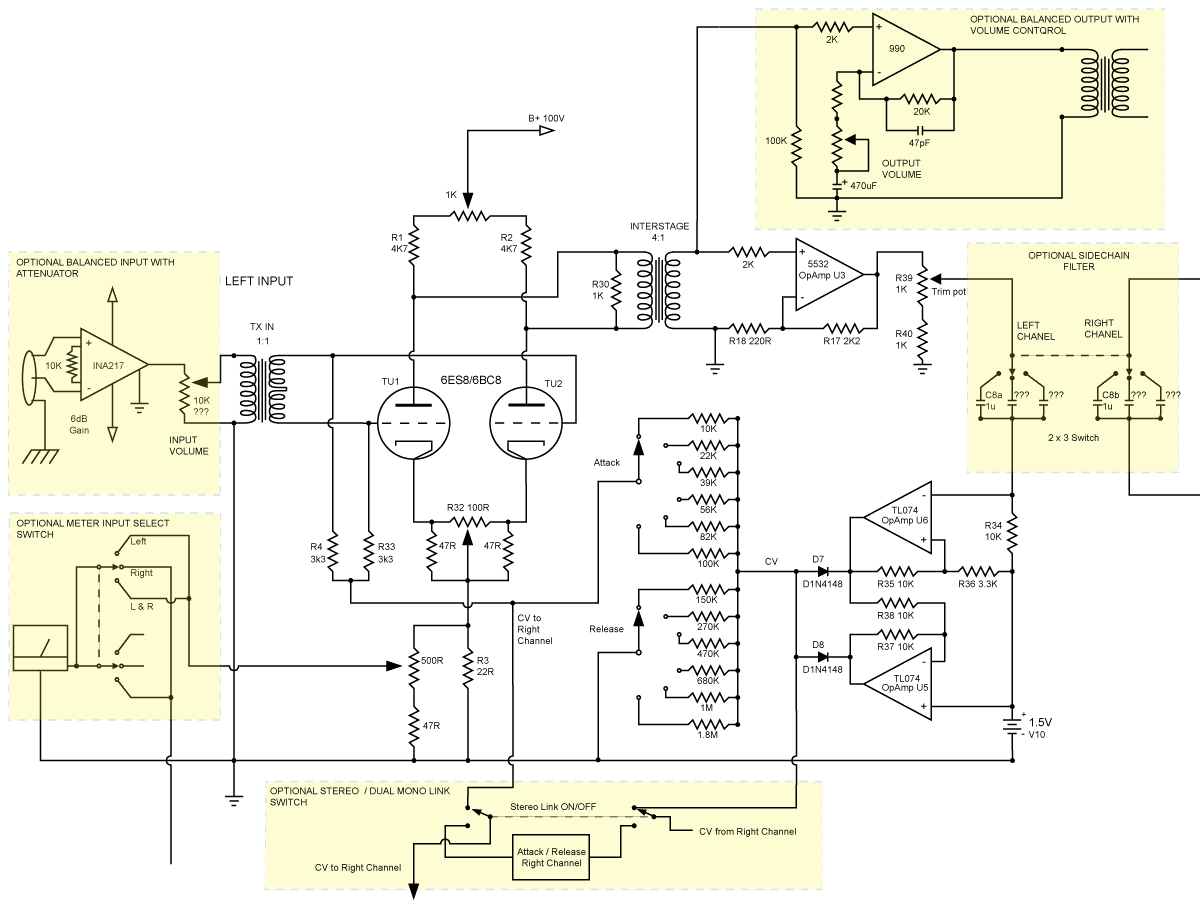
Well, I did some experiments with the interstage transformer. First one I tried was a Hi-Z Haufe transformer ( "ST-3135" look here for a datasheet:http://audio.kubarth.com/rundfunk/index.cgi#trafos )from a Lawo Amp card. It worked pretty well, but you have to load down the tube a lot for a good frequency response, like prr did, I used 2,5k instead of the 1k he used, but you still need a lot of gain afterwards. The tube I use is a pcc189, by the way.However, there is still no confirmation on what would be good transformers. Bluebird says the Edcors are no good but maybe the big ones used in the PM660 will work. Illacov is gonna try some Cimemag TX. I hope he gets some good results with them.
Selecting the right transformers for this project is still whats confusing me.
Gain is cheap, says prr, but it still introduces noise, and it seems to be more elegant to use the possible gain of the first tube stage to your advantage.
And I also wanted to get rid of the plate resistors to have the compression a little less soft knee. When you dive into compression and the tubes are running with much less current, the voltage across the plate resistors gets higher (Ohms Law), the tubes amplify more, and kind of counteract the gain reduction happening with the grid bias voltage. Of course this not a problem per se, the old Urei comps work and surely sound fine.
So I ordered two Lundahl 1660s, which is a real interstage, where you can feed the plates through the primaries.
Wiring it 1:1 and fiddling a bit with the load resistors, I got a great frequency and distortion response in all compression stages (A slightly better bass response than with the Haufe, but just a little) and the compression characteristics are very much to my liking. Of course the Lundahl is 90 Euro a piece, but I think it is worth it.
The output buffer is not so much for gain (only 6-10dB) but impedance matching now, and the 5532 in the sidechain needs less gain, too, of course.
Experimentation is your friend with those compressors, so I went a little further. I wanted to have a tube output stage so I had four tube sockets installed and the power supply was rated for four tubes, too. I started with the Lawo tranny and two e88cc as a srpp stage (20dB gain). It worked, but as I said, I wanted the sound a little bit different.
Then I bought the Lundahls, I had more gain available from the first tube stage, I wired the the e88cs as cathode followers, which is unity gain, but less output impedance and better driving characteristics into difficult loads. Another advantage was, that I had a balanced signal path throughout the compressor and virtually no background noise. Well, besides of not having enough gain now, it did not sound good to my ears, even though it measured well, the compressor sounded a little bit choked, maybe my implementation of the cathode follower stage was less then perfect, or the output transformer I used did not like the output impedance of the tubes, I don't know.
Then I tried the discreet lawo opamps I had lying around as buffer amps and things sounded better again.
Now I had two tube sockets without use so I wired two tubes parallel per channel, like the poor man does. I have enough pcc189 lying around from the matching procedure.
It reduces the output impedance the interstage transformer sees, which helpes the distortion charcteristics and the frequency response.
The compressor has less than 0.2% distortion at 100 Hz and +4 dBu and is -0.4 dB at 30 Hz now, which is pretty good, I think.
It sounds very natural and open now.
But the solid state sidechain from prr is not able to drive that tube arrangement into heavy compression any more. -8 volt on the grid are rather 11 dB gain reduction now and not 18 dB, like before with one tube. (But I do not really need more than 10dB of Compresssion ever) And you have to modify the sidechain with a tl072 buffer and a grid resistor behind the timing network if you like long release timings, because of the maximum grid resistance two paralleled tubes like to see. The release pot would show the tubes too high a resistance.
Another thing I did is a feedforward/feedback switch. When you drive the sidechain feedforward (like the LA2A), the compressor behaves very different than stock. While the compression ratio is like 2:1 the first 5dB and maybe 4:1 the next 5dB in the feedback mode, it is much more brutal in feedforward. At least 1:4 the first 5 dB and after maybe 8 dB of gainreduction the ratio is going negative in my compressor (more signal in = less signal out). Attack and release characteristics change too with feedforward, everything seems to get a little bit unpredictable, but moderatly used feedforward sounds awesome and is a keeper for me.
Well, that was a lot of writing and thanks for listening, but as I said, if you try some things, you can get pretty far with this design, and right now, this is my favorite compressor.


