question about fader and its amplifier on the same board

GroupDIY Audio Forum

Help Support GroupDIY Audio Forum:

This site may earn a commission from merchant affiliate links, including eBay, Amazon, and others.

Dimitree

Well-known member
Joined
Jul 26, 2011
Messages
127
I noticed that usually in medium/big consoles, the fader is not mounted on the same PCB with the rest of the channel circuitry, but is wired using cables.
I guess it's for two reasons:
1) the faders are large and can't be directly mounted on the PCB
2) the panel with the faders usually sits at a different angle than the rest of the controls
The issue then (as far as I've read) is that the wire needs to be short and possibly shielded (probably because the wiper/opamp input connection is at high impedance?)

While building a small home console, I'm going to use cheap PCB mounted slide potentiometers instead of proper faders (like those: link).
So I'm wondering, instead of placing the post fader opamp togheter with the rest of the circuitry (preamp, aux potentiometers, pan, etc), can I just put the post fader opamp as close as possible (or directly under the fader, since I'm using SMD opamps) to the "fader" terminals, on the same PCB of the faders?
and then I don't have to worry about the lenght/kind of wiring between the "main board" and the "fader board" because all the signals are now low impedance.
And of course I will need another connector to provide +V/GND/-V.
Being both the main PCB and the fader PCB horizontal and parallel to the control panel (and not perpendicular like common channel strips) I could group 4 or 8 channels on the same PCB and so just run a single connector from/to the fader PCB instead of using a connector for each fader.
Is that right or I got it completely wrong?
sorry if what I am saying is dumb, I'm still learning!
thank you!

Screenshot 2024-11-20 at 17.27.41.png
 
Everyone who has ever built a decent sized mixer knows there is one hell of a lot of wring involved. And you vow that next time you build one you are going to do everything you can to reduce or simplify the amount of wring. So including the fader wiring for four faders in one connector is a good idea. Technically I see no real problems with the scheme you have outlined. Just make sure to adequately decouple the op amp at the chip. 10uF should be sufficient as well as the usual 100nF. Also, at the moment the dc bias for the non-inverting input comes directly from the fader wiper. This is a recipe for noise and scratchiness. Connect the non-inverting input to ground via a resistor (say 100K) and couple the fader wiper to it via a capacitor. Again, 10uF should be sufficient with a 100K bias resistor.

Cheers

Ian
 
thank you really much for the reply Ian!

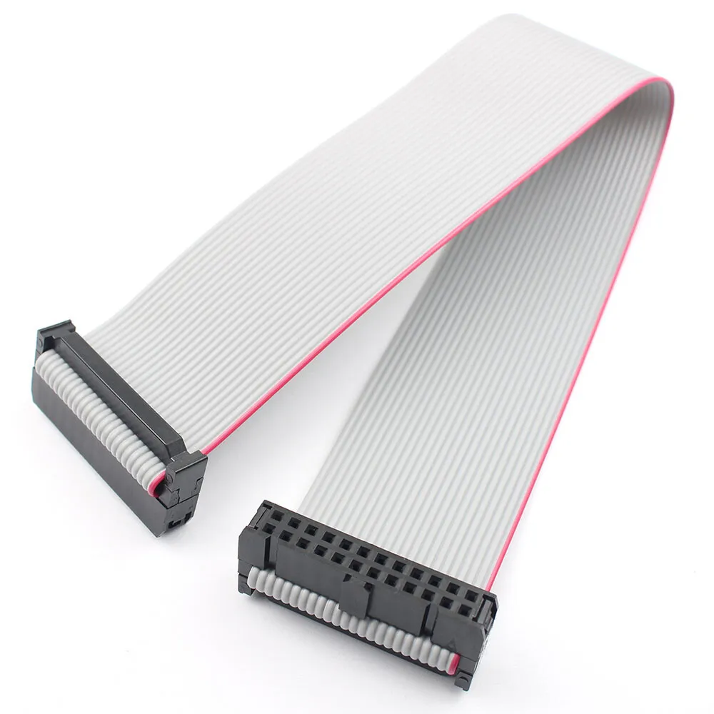
what do you think about using standard ribbon cable for this task? like this (but much shorter)
DS3815RCC1BL099.jpg

how would you assign the fader connections to the pins? I was thinking about alternating wiper_channel1/GND/post-fader-out_channel1/GND/wiper_channel_2 and so on.. Is that overkill? maybe a single GND connection for the whole connector, to avoid loops?

about the capacitor between the wiper and the opamp input, I omitted it based on suggestions here: https://groupdiy.com/threads/post-fader-amplifier-questions.85727/page-4#post-1127126
I hope I didn't misinterpreted that suggestion in the first place, so I'm going to checking again
 
Smaller value (inexpensive) mixers generally have the faders and as much as possible wave soldered to single PCBs. Larger and more expensive consoles for sundry reasons break out the faders generally using 3-4 conductor shielded cable.

It is fairly common to build in +10 dB of post fader gain. When using a differential input op amp you can forward or back reference the local fader ground to the sending signal or to the receiver. When designing a premium console fader kill is specification of interest. A differential receiver can help deliver good fader kill (how off it gets when pulled down).

JR
 
thank you really much for the reply Ian!

what do you think about using standard ribbon cable for this task? like this (but much shorter)
DS3815RCC1BL099.jpg

Ribbon should be fine. The distances are short and the sources are low impedance so screening is not so important.


how would you assign the fader connections to the pins? I was thinking about alternating wiper_channel1/GND/post-fader-out_channel1/GND/wiper_channel_2 and so on.. Is that overkill? maybe a single GND connection for the whole connector, to avoid loops?
You want the lowest ground impedance you can get so the more grounds connections the better. You need to separate send and return signals with a ground to minimise capacitive coupling between them. Every other wire as ground is not a bad idea.
about the capacitor between the wiper and the opamp input, I omitted it based on suggestions here: https://groupdiy.com/threads/post-fader-amplifier-questions.85727/page-4#post-1127126
I hope I didn't misinterpreted that suggestion in the first place, so I'm going to checking again
The op amp needs a dc bias resistor for sure. If the fader wiper ever accidentally become open circuit all hell will break loose. I am not an op amp expert so quite possibly with modern FET input op amp you can get away without an input capacitor. But I would put one in. (you can always replace it with a wire link).

Cheers

Ian
 
Go for Alps faders instead of those cheap carbon Bourns ones, they are very fragile to downward pressure (as when fitting fader caps) as the carbon track is easily damaged.

My electronics prof told me some ,1uf ceramics in parallel to the bigger bypass electrolytics is good for minimizing noise.

I can only second the wish to minimizing wiring when building a console; a PCB for the fader(s) with idc connections to the rest of the circuits minimizes wiring substantially.

Sure shielded wiring might be preferential, but don't underestimate the pain of working with small wire to board connectors like kk molex style etc; a bad crimp is way worse than slightly higher noise figures imo. Use terminal blocks and ferrules instead, much easier to form a reliable connection.
 

Latest posts

Back
Top