[Go to second page to see the pictures of the completed project]
Hi Everyone,
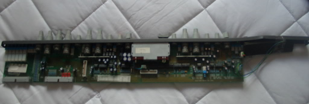
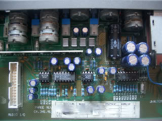
My first project will be racking an Amek Einstein channel strip, Im just starting my way into DIY and electronics so I will need a lot of your help. Please give a hand, and have some patience with me.
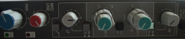
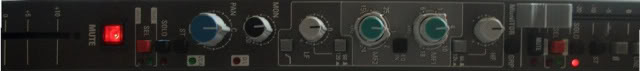
The channel Strip has 2 separate channels with individual EQ, one channel is mic/Line and the other is the Monitor (tape return).
I have the schematics and diagrams for the module.
I also have a power supply.
My Goals are:
- Rack the module into a 1 unit rack , having the power supply externally
- Use the input on the channels, and have outputs before (insert send) and after the fader
- Maybe modify the tape return channel to a mic/line input, since I have a couple of SSM2016 , the same chip used on the pre channel of this module.
- Getting rid from the Aux’s, Bus outs, Pan Pot, Mute switch , etc … Basically everything that I don’t need and is in the signal way
So Far:
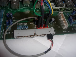
-I have connected the Power supply to the card : -17,5v, 17.5v, 48v, 0v, chassis ground
-All the connection work, I can get audio going into both to the Mic and line inputs. Phantom Power is working also
-I can get the audio out of the module from the channel Insert send (unbalanced output)
My questions for the next steps are:
1) How could I take an output after the fader? Where should be the best place?
2) What should be the best way to Balance the outputs? Should I do this or keep it unbalanced?
3) Is the input on the Monitor channel the same as a Line input? What would be the easiest way to modify it to a Pre-amp?
4) I measured the rails of the power supply, and instead of + 17.5v and – 17,5v I have +17.2v and -16.9v . Is that any problem that the rails are not exactly 17.5 volts? Would the audio performance from the preamp improve ?
Schematics are here:
Page 1
http://i299.photobucket.com/albums/mm284/Amekeinstein/AmekEinsteinSchematicPage1.jpg
Page 2
http://i299.photobucket.com/albums/mm284/Amekeinstein/AmekEinsteinSchematicPage2.jpg
PCB Layout1
http://i299.photobucket.com/albums/mm284/Amekeinstein/einsteinsheet1.jpg
PCB Layout2
http://i299.photobucket.com/albums/mm284/Amekeinstein/einsteinsheet2.jpg
Hi Everyone,
My first project will be racking an Amek Einstein channel strip, Im just starting my way into DIY and electronics so I will need a lot of your help. Please give a hand, and have some patience with me.
The channel Strip has 2 separate channels with individual EQ, one channel is mic/Line and the other is the Monitor (tape return).
I have the schematics and diagrams for the module.
I also have a power supply.
My Goals are:
- Rack the module into a 1 unit rack , having the power supply externally
- Use the input on the channels, and have outputs before (insert send) and after the fader
- Maybe modify the tape return channel to a mic/line input, since I have a couple of SSM2016 , the same chip used on the pre channel of this module.
- Getting rid from the Aux’s, Bus outs, Pan Pot, Mute switch , etc … Basically everything that I don’t need and is in the signal way
So Far:
-I have connected the Power supply to the card : -17,5v, 17.5v, 48v, 0v, chassis ground
-All the connection work, I can get audio going into both to the Mic and line inputs. Phantom Power is working also
-I can get the audio out of the module from the channel Insert send (unbalanced output)
My questions for the next steps are:
1) How could I take an output after the fader? Where should be the best place?
2) What should be the best way to Balance the outputs? Should I do this or keep it unbalanced?
3) Is the input on the Monitor channel the same as a Line input? What would be the easiest way to modify it to a Pre-amp?
4) I measured the rails of the power supply, and instead of + 17.5v and – 17,5v I have +17.2v and -16.9v . Is that any problem that the rails are not exactly 17.5 volts? Would the audio performance from the preamp improve ?
Schematics are here:
Page 1
http://i299.photobucket.com/albums/mm284/Amekeinstein/AmekEinsteinSchematicPage1.jpg
Page 2
http://i299.photobucket.com/albums/mm284/Amekeinstein/AmekEinsteinSchematicPage2.jpg
PCB Layout1
http://i299.photobucket.com/albums/mm284/Amekeinstein/einsteinsheet1.jpg
PCB Layout2
http://i299.photobucket.com/albums/mm284/Amekeinstein/einsteinsheet2.jpg