Racking Channel Strips Audio Developments UK

GroupDIY Audio Forum

Help Support GroupDIY Audio Forum:

This site may earn a commission from merchant affiliate links, including eBay, Amazon, and others.
Hey Ritz,
I am sure together we can figure this out!

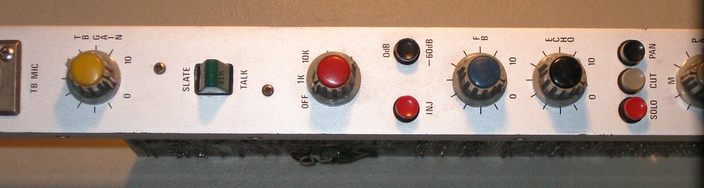
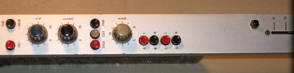
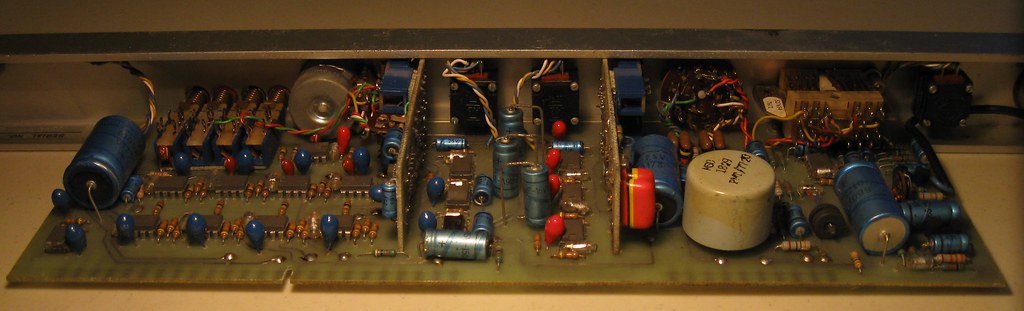
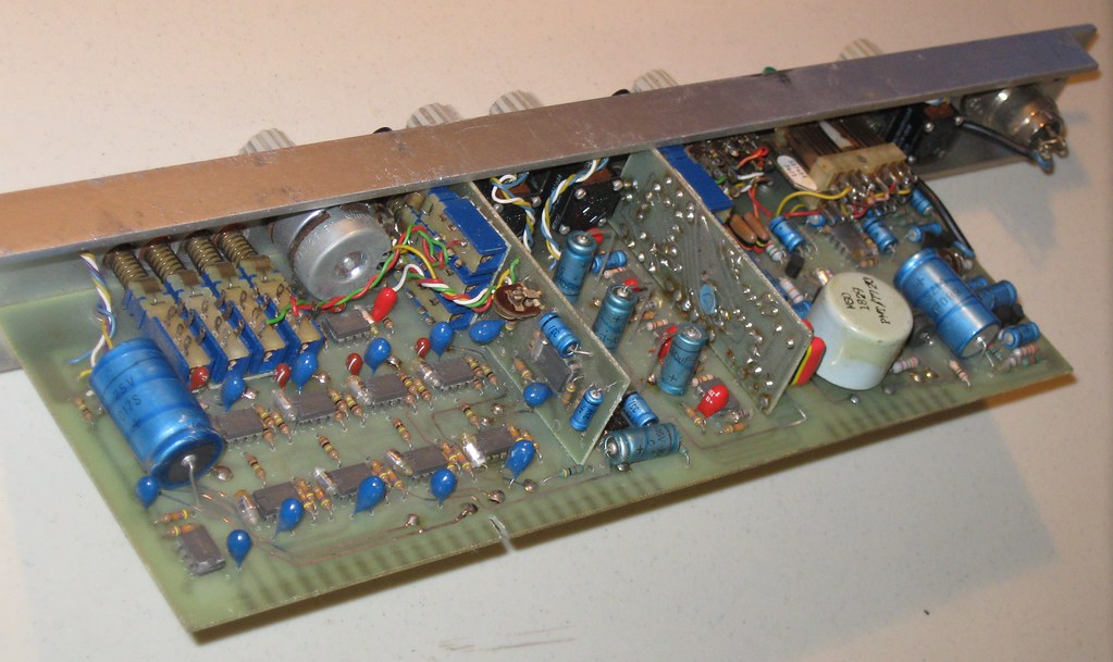
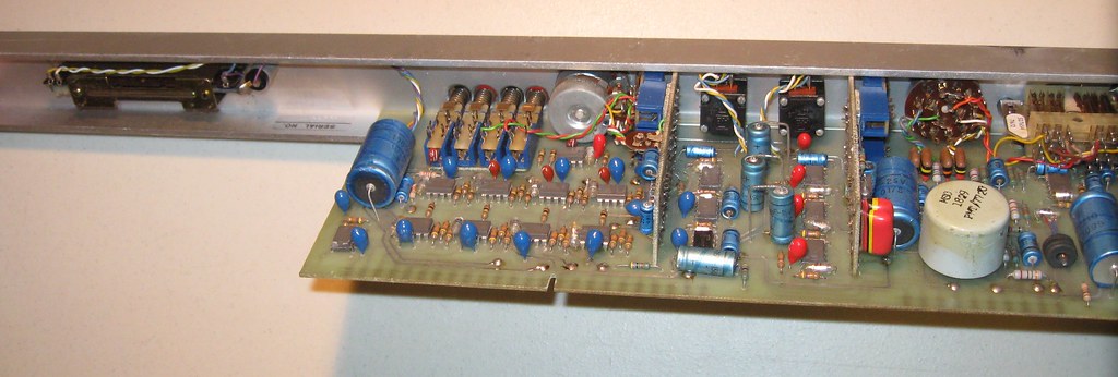
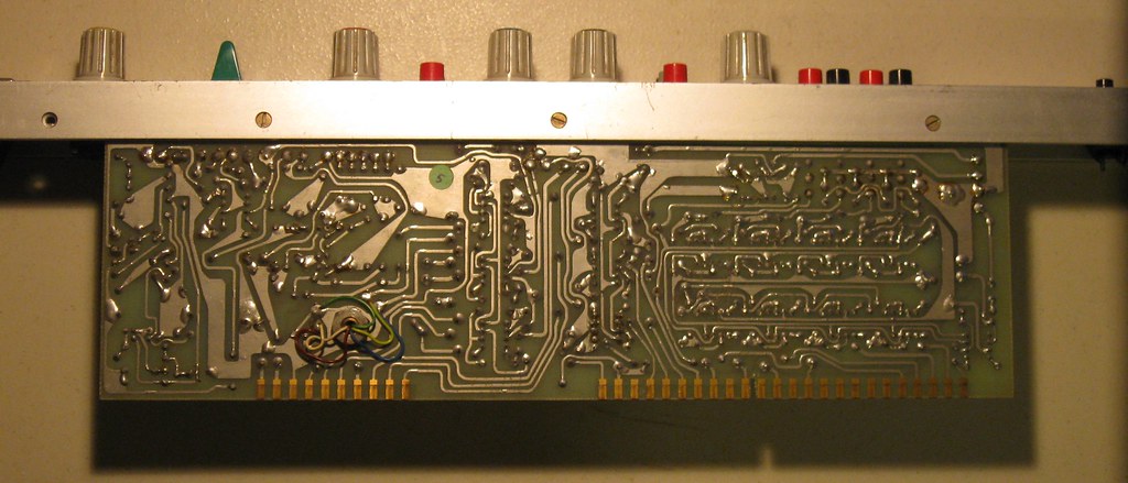
Regarding pins 4 and 5, the fact that there's a positive and negative line input connection suggests that the line level input is balanced. I'm not sure, but is this usually the case with line inputs on mixers? I always thought these would generally be unbalanced inputs. Also, the connection from pin 5 to the blue wire on the FB pot and the fader has me baffled. And pin 29, I wonder if this would be a 'direct' channel out.

Yes, I agree both obvious oversights on my behalf. Pin 4 seems to be pre-eq and pin 5 post eq. Perhaps one is an insert? I guess this would need two pins (send - return) and a shared audio ground (could be pin 3) though...Pin 29 being a 'direct' out makes good sense.

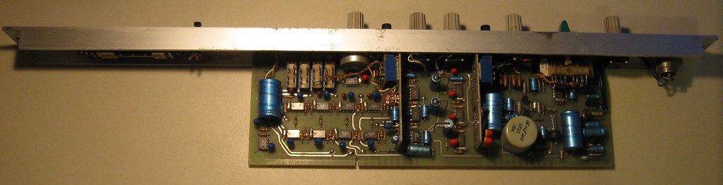
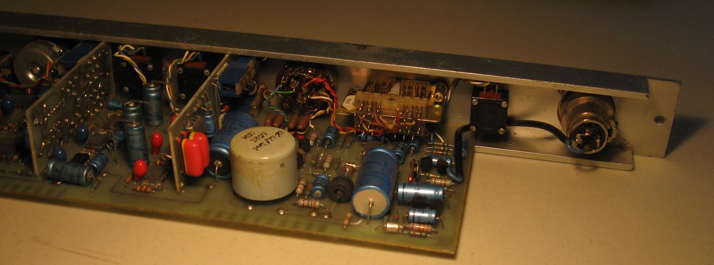
I think I need to just get a hold of a bipolar power supply, connect it to a channel and then play around with feeding some signal through the input. That would help answer a few questions and also help to unlock how all the panning and buss send connections are routed and how they correlate to one another.

Yes, I agree. I just havent been brave enough yet to apply Volts
11 :)

also, How did you insert the pics?? I can only seem to attach pics via the additional options tab when I post!
Mac.
 
mac said:
Hey Ritz,
I am sure together we can figure this out!

Amen to that!  :D


Yeah, the pin 4/5 thing is a bit of a mystery. I'm thinking having a specific post-EQ insert on this strip would be redundant, as I would think you could achieve the same effect by having a pre-EQ insert and then just switching out the EQ section via the “EQ” switch. I think pin 4 is still looking a lot like a line level input; pin 5 I'm no so sure about. The way pins 5 and 29 are tied to the fader, I wounder if there is maybe some kind of pre-fade/post-fade output business going on...  ???
Anyway, more digging will surely yield some answers.

For the pics, I first uploaded them to an external free photo hosting site. In my case I use www.flickr.com but there are others like www.photobucket.com. Then, to post a  picture, you simply use the bulletin board's image tags “http://[/img ]” (but without the spaces) and insert the URL of the pic in question between those tags. So it'll look something like this in the reply window: [img ]http://URL address of the pic in question[/img ] but again without the spaces. Hit preview post and the pic should come up in your preview. The reply window also has a button which inserts the image tags for you to save you the hassle of typing them out (second button from left on the bottom row of buttons). Not sure if this explanation is making sense; let me know if it's not.

Anyway, here's a pic of the top side of the LED display PCB. No logic chips here...

[img]http://farm3.static.flickr.com/2533/3680561849_4e0bb0110d_b.jpg
 
Also, here are the links to those 748 datasheets:

http://www.datasheetarchive.com/search.php?p=1&q=748
(Scroll a third of the way down the page and there is a general info sheet from 'Intersil Corporation' and a datasheet from'Raytheon Company'. Both in PDF format.)

http://www.national.com/ds/LM/LM748.pdf

http://www.national.com/mds/LM/MNLM748-X.pdf

The last two PDFs come from National Semiconductor's 748 page: http://www.national.com/mpf/LM/LM748.html
 
This is not an overseas production, look at the capacitors etc. and you will know that this is european made.

So when it is neither a Jands nor a Nova Sound channel strip, what can it be then ?

Here is the answer.  Compare the "outfit" with this mixer:

AudDevelop_AD-031.jpg


and you will know, that this is a "Hot British" Audio Developments channel-strip.

Here is the manual (including the schematics) for the shown mixer and some other vintage Audio-Developments stuff too:
http://www.audio.co.uk/I1.htm

Hope this helps,

analogguru
 
Hey Ritz,
I have emailed Audio Developments in the UK to see if they can provide schematic and make and model info. Looks like it might run on + - 12v, so I am glad I didnt get trigger happy and feed 15 down its throat.

Since these guys are producing mainly location recording gear for film and TV, this might explain a few things - RE functionality of the strips...

Keep you posted,

Mac.

P.S. i suppose i should try to rename this thread now, to see if we can attract more owners of Audio Developments gear....might help...
 
Sorry guys, hectic week so my reply is a little late...


analogguru,
Thank you, thank you, thank you!!! Yes, it certainly does help... finally we've got something!  :D
I second Mac on the virtual carton of beer!


Anyway, here are just some observations so far:

From what I can see, our unidentified mixer seems closest to the AD-031 in the Audio Developments archives page (which is also the same mixer in the pic that analogguru posted). Most of the other mixers in the archives are newer, generally dating to the the late 80s, and use more modern opamps, etc. The AD-031, however, also uses 748 opamps and those same “MSC 1829” input transformers. Also, the AD-031 shares the same type of knobs and also has the manufacturer name only printed on the master module, not on the input modules (the later ones I've seen all look like they printed the name on each input module as well).

The AD-031 also seems to share a lot of circuit similarities and isosyncracies. For example, the two inductors between the phase change switch and the mic/line input section (marked “La” and “Lb” on page 33 of the PDF manual). On our unidentified mixer you can see these inductors located on the PCB between the rotary gain control and the input transformer (those two little upright coils covered in greyish plastic).

On the surface, our mixer looks like a more “complex” or feature packed version of the AD-031. Sort of like the AD-031 with a more complex EQ section, more buss routing options, and a few other extra features. I'm still yet to determine how closely these similarities translate on the circuit level.

Most of the newer Audio Developments consoles seem to run off 12V, but the AD-031 runs off 24V. That's 16 D-size batteries for portable use (yikes!). I'm going to guess our unnamed mixer will be similar.

Looks like I was off on the Australian Trimax transformer thing, even though Trimax used those “MS” and “PMT” designations on their transformers too. Maybe this is some kind of nomenclature common among manufacturers?

Here's an AD-031 (ebay completed listing) with a bunch of quite detailed pics. Pretty interesting: http://cgi.ebay.co.uk/AUDIO-DEVELOPMENTS-AD-031-BROADCAST-QUALITY-MIXER_W0QQitemZ320389445723

Just for comparison's sake, here are some typical Jands and Nova Sound mixers from back in the day. Not a lot of similarities there really...
Jands: http://cgi.ebay.com.au/VINTAGE-SOUND-MUSIC-MIXER-JANDS-ELECTRONICS-AUSTRALIA_W0QQitemZ260432232439
Nova Sound: http://cgi.ebay.com.au/Nova-C8-8-channel-mixing-console_W0QQitemZ110411029760


Mac,
Let me know what Audio Developments have to say on this one...
My concern is that if schematics and documentation does indeed exist for this model, then it would already be posted on the website. We'll see though...
It looks to me like the documentation of the AD-031 is a bit lacking on the input module side. There appear to be a lot more schems and circuit diagrams for the other parts of the console (summing, master section, power supply...) than the input section.
I might also email them in the near future once I have all my thoughs/questions compiled.


Cheers,
Ritz
 
Hey Ritz,
good to hear from you. I am still waiting to hear from Audio Dev in the UK. I have resent the email just today and am yet to make contact. :mad:

I concurr with your post on many fronts, and came to similar conclusion about the AD-031 being the closest match, however it is frustrating that our strips are still different. I am hopeful that in time these additional features which hinder us now, will reward us in the end...

I will keep on their case and once I make contact I will let you know.

Mac.
 
This mixer looks to me very close to an AD008, although I don't recognize the mic pre, which used a quite uncommon circuit using discrete transistors (no IC's) where the secondary of the mic xfmr is connected in the feedback loop, thus reducing the input impedance, but also made the mic pre silent when the mic was disconnected. The 748's were typical appointment in the AD mixers. The AD008 ran on a single 24V rail (on batteries since it was originally a location mixer). This one is clearly different, with its strange routing concept.
 
Thanks for your input AbbeyRd.

I just got an email from Audio Developments, they advise;

"they are obviously audio development strips but nobody here remembered them at first but they are channels to an AD 075 mixer, this design was we believe to be the first flexible group mixer manufactured in the early 80’s You could designate the channel as an input or output group- the 7 segment indicator showing which group A, B, C or D.
Now for the bad news we can not find any documentation on the mixer. I know it was powered with 24V DC and needed an external 48V for the Phantom but we have nothing on the pin outs
If I can be of any other assistance please call"


So looks like it is up to us now eh Ritz!!

Mac.
 
Abbey Road,
Cool info, thanks very much for that!

Mac,
Nice work! The lack of documentation is going to make things a bit tricky but at least it's something; we have a model name and some voltages. Hopefully what we have here and the service manuals of the other AD mixers will help us piece this one together. That thing about the strips being assignable between input and output channels is very interesting indeed. I wonder how this is realised in practice with that funky switching scheme, and what kind of jack connections are required to make it happen...
Also, I'm going to guess that the 24V supply is split into +/-12V on the actual channel strip PCB for supplying the opamps.
 
Just a little tid-bit... found another AD-031 on ebay with some nice pics: http://cgi.ebay.co.uk/ws/eBayISAPI.dll?ViewItem&item=290330250518

Just regarding the date of our console strips, in that letter from Audio Developments they mention it being from the early 80s. I still think they're actually older than this. I'm no expert, but I'm pretty sure those 748 opamps were out-dated even in the early 80s, and there were already plenty of much, much better opamps for audio available at that time, such as the 5534. I can't really see a quality console manufacturer using the 748 for such a 'critical' role in the early 80s. I think I've mentioned it earlier in this thread, but the date codes on the 748 opamps point to 1974, and I think this seems a more accurate age for these strips. Indeed, the AD-031 in the above auction says it's from 1975 and it better matches the era of our strips. I kind of have a feeling our channel strips actually came slightly before the AD-031. My reasoning here is that the AD-031 (and every other subsequent AD console I've seen) use full 100mm throw P&G faders. Our strips use those 75mm, open-frame Ruwidos -a bit of a step back. I can't imagine the manufacturer moving from the P&Gs to the somewhat more primitive Ruwidos; starting out on the Ruwidos and moving up to P&Gs would make more sense to me. But that's just a hunch, so who knows...


284104096_o.jpg


284104552_o.jpg
 
Ritz,
Yes I have been hunting too, and I think I would agree with your reasoning on this. I noted the change in the use of 100mm faders also. In fact I havent located a photo of one utilising 75mm faders.

Gee, these things are like landrovers in terms of thier styling not changing for a long time!! Makes the job of identification from the exterior a little bit harder.

Mac
 
More news via email from Tom at Audio Developments;

Good news we have found some circuits, they are old and a big size but if you can wait a couple of days I will get them scanned and sent to you, have you got the whole mixer or just the input strips?
Regards
Tom


Fingers crossed, I shall post as soon as I get them. ;)

Mac
 
Wow, great news Mac!

I just recently managed to buy a couple more of the input modules off one of the other guys who also bought these on ebay... Among these was the talkback/tone module from the original mixer.
As you can see, in the talkback part, there's an XLR plug for talkback mic input, a gain pot (smooth turnng, not stepped like the input modules) and Slate/Talk switch (momentary switch)... the slate function is similar to talkback, except it allows you to talk directly to the recording medium (ie: tape) so you can make verbal notes/introductions to different takes.
Then there's an oscillator tone function, switchable between 1K and 10K. The "INJ" button I believe "injects" the oscillator tone, and the "0dB/-60dB" button sets the oscillator to either one of those two levels. FB, Echo, Pan, Group/Buss and Solo knobs and buttons appear the same as the input modules, however the "CH" button on the input modules in replaced by a "Cut" button here.

The PCB on this one is choc-a-block full of 748s... 19 in total. And you can see the area behind the A, B, C & D switches consist of a large bank of these opamps, so the wiring scheme for the group/buss section is quite a bit different to that on the input modules. I know they're pretty lousy by today's standards, but I can't help but wonder how much all these 748s would have cost back in 1974. Also, you can probably see in the pics, the pinout configuration and PCB-edge-shape is different to the input modules too. Unfortunately things are pretty busy around here at the moment so I won't really get a chance to properly dive into this project until probably August sometime; I look forward to it though!

Anyway, that's great news on Audio Developments finding more circuit info. Hopefulluy that'll make our job a bit easier!  :)


Here are some pics:

3715837607_1a6d2b90c8_b.jpg

3715839503_84cea26242_b.jpg

3715840433_3a58cd61a2_b.jpg

3715839975_834e747299_b.jpg

3715837269_df196063e1_b.jpg

3715833097_45e0759ed0_b.jpg

3715832447_e15a3cb756_b.jpg

3715846483_d167496e90_b.jpg

3715844107_21577c51a1_b.jpg

3716655860_055a6ca738_b.jpg


Excellent score on those other channels Ritz.

I have some more info from Audio Developments. See attached schematic. There was some more pages from Tom, but the document is too big to post here. I shall send them to you via email Ritz.

Now to pursue a 0v +24v +48v regulated power supply...

Mac. ;)
 

Attachments

  • AD075 Schematic INPUT Strips.pdf
    181.7 KB · Views: 54
Mac, that's excellent, PM sent!

Regarding power supplies, those voltages are actually quite handy as they're the same voltages used for most of the old Neve stuff (as well as a bunch of other brands). The implication for DIYing being that there tend to be a lot of projects floating around for those kind of power supplies. I haven't really gone through it in detail yet, but the power supply meta thread in this forum looks like it might be pretty useful: http://www.groupdiy.com/index.php?topic=2665
 
OK so I have had these on the bench over the last few weeks.

I have now got them powered up 24v, 0v, 48v. Installed modification to enable phantom power switching and installed led indicator on each strip. Everything works as expected and sounds OK with test signals but output however is very low level. Microphone connected yields almost no output at all.

Can anyone explain what is meant by the last symbol on the output "6". It looks like one side of a transformer, but in the console I presume that the input strips would have fed the input of the master fader.

Will I need to modify the output amp stage to bring the gain up?

full schematic is further back in this thread...

thanks for any input ...Mac.
 

Attachments

  • AD075 OUTPUT stage.jpg
    AD075 OUTPUT stage.jpg
    41.6 KB · Views: 41

Latest posts

Back
Top