Rail splitter for variable state filter VGND

GroupDIY Audio Forum

Help Support GroupDIY Audio Forum:

This site may earn a commission from merchant affiliate links, including eBay, Amazon, and others.

domingo

Well-known member
Joined
May 10, 2021
Messages
68
Location
Berlin
Hi Friends,

I need to provide VGND to a certain amount of EQ filters (4) and need to anticipate how much current will they drag from a rail-splitter circuit.

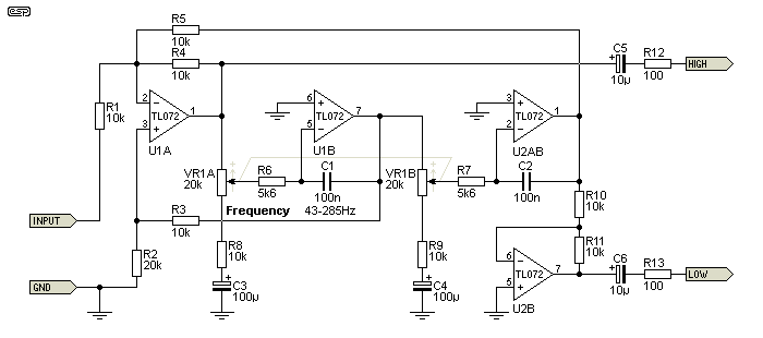
The EQ circuit is a traditional variable state filter as follows: https://sound-au.com/articles/st-var-f2.gif

I need to power 4 of these simultaneously and the opamp in use is an AD712 –both for the rail-splitter and 4xPEQ. The AD712 consumes 5mA per opamp and can output up to 25mA per opamp. 4 PEQ circuits need 8x AD712 in total, which in theory consume 80mA all together, but I presume not all this current will be consumed by the VGND.

Can somebody predict how much current the VGND would actually consume? I'm trying to guess here which rail-splitter circuit to use and keep it minimal, before I can reach any board design. Working DC voltage is 12v (+6v/0v/-6v).
 
That circuit looks like it has a few 30K-ish resistances to ground which in parallel would be 6K or so. So 4 in parallel might be 1.5K worst case. So 6V / 1.5K is 4mA max. There might be some arrangement of controls and confluence of circumstances where you get some kind of low point in the impedance that might draw more. But +-4mA is probably a good initial assumption. Noise might be an issue though. A large cap between VGND to the outer 0V might be important for noise performance. Although AD712 does not look like a low-noise part so maybe it won't matter.
 
st-var-f2.gif


C3 and C4 can reference to 0V rather than V+/2 to reduce AC signal current in the rail splitter.

If U1B, U2A and U2B's non-inverting inputs and the port labeled "GND" reference to V+/2 then the DC current in the rail splitter will be relatively small.
U1B's output will be at V+/2 so there shouldn't be significant DC flow through R2/R3.
(R3 looks to be bootstrapped at DC when the ground port becomes V+/2.)
Signal current will flow through R2/R3 however.
 
Thank you all! You rock guys and saved a bunch of measurements and experimentation-time.

If overall consumption will be around 4mA I wouldn't worry about it, since a splitter on half AD712 will be more than enough. Right?

Noise is indeed important, I just like the sound of these opamps. I'm thinking of the following rail splitter circuit for all four EQs, trying both to reduce noise but also need to keep it simple(r). I mean to get rid of unnecessary caps indeed for case limitations.

EDIT: My power source are LiIon batteries in series, case it matters, btw.

C3 and C4 can reference to 0V rather than V+/2 to reduce AC signal current in the rail splitter.
Thanks for that, I'll take it into consideration.
 

Attachments

  • railsplit.jpg
    railsplit.jpg
    48.7 KB
Last edited:
EDIT: My power source are LiIon batteries in series, case it matters, btw.
Do you have access to individual cells? If yes, you could get your center tap from the mid-point of the cells. As long as current draw is symmetric, that would work best. No VGND necessary.
 
Do you have access to individual cells? If yes, you could get your center tap from the mid-point of the cells. As long as current draw is symmetric, that would work best. No VGND necessary.
Unfortunately I have only 3 batts available for the design (which is portable, very small case and lots of stuff inside). Together they give 12-11v as they discharge and other preamps are powered by the same pack simultaneously. I'm stuck to the splitter therefore, but the scheme above is really based on diagrams I've found around. Tried with the bare opamp and two 100k resistors and it worked fine with one EQ filter, but puzzled about the importance of the caps.

Thanks for your support as usual!
 
Most op-amps can't drive large capacitance directly without going into severe oscillation. The AD711 makes a point that the design settles in under 1us while "retaining the ability to drive a 100 pF load capacitance...."
If they were proud that it kept working properly with a 100pF load it is unlikely that it will continue operating properly with a million times higher capacitance on the output.
Oh! Good to know. Output caps out then and live with the noise-if any.
 
Try this. The output is isolated from the caps, anything from 20-100R is good, plus if you put a small FB resistor, the amp won't be a full gain/unity and won't be in that unstable range. Since the virtual ground is only for the offset of other amps, their isn't much current. Short the output after the 100R and check the op-amp for HF oscillations. Worst case you might need a small FB cap.
 

Attachments

  • railsplit.jpg
    railsplit.jpg
    51.1 KB
Try this. The output is isolated from the caps, anything from 20-100R is good, plus if you put a small FB resistor, the amp won't be a full gain/unity and won't be in that unstable range. Since the virtual ground is only for the offset of other amps, their isn't much current. Short the output after the 100R and check the op-amp for HF oscillations. Worst case you might need a small FB cap.
Thank you. Are both C78 and C79 fundamental? Or a cap at the V+ pole (C78) would suffice?
 
if you put a small FB resistor, the amp won't be a full gain/unity and won't be in that unstable range
Not sure what you were trying to say here. The AD711 is not a current feedback amp, it is a traditional voltage feedback design, so I don't see that adding a resistor does anything except add an additional pole with the input capacitance, which would tend to worsen stability, not improve it. For a unity gain buffer the easiest layout is just a short trace from the output back to inverting input directly under the op-amp.

Since the virtual ground is only for the offset of other amps, their isn't much current.

Not much current, but it is still in the signal path so the bandwidth of the virtual ground directly affects the bandwidth of the circuit. With an RC circuit in the (virtual) ground path, be sure to check total circuit response at high and low frequencies and make sure the values you are using don't cause any changes in frequency response where you care.
 
Thank you!

This is the working solution so far, following all your comments :)
 

Attachments

  • Screenshot 2022-03-31 at 12.27.07.png
    Screenshot 2022-03-31 at 12.27.07.png
    33.8 KB
Thank you!

This is the working solution so far, following all your comments :)

Is there any particular reason that you've lost the capacitor from the junction of the 100K divider resistors to Ground ?
You had it at 100n previously. In fact I'd make it a lot more than that (although I understand that there is an associated ramp up time on power up).
It's essentially standard practice in anything I do that uses a static reference voltage derived in that way.
With a larger capacitor there then fwiw I'd question the need for the capacitor on the OpAmp output. At least questioning the need for a capacitor in the uF range.
It's function is essentially replaced by the capacitor at the potential divider and the power rail is already bypassed with a large capacitor.
Bear in mind that the function is not really a "noise filter" but more "rail decoupling" to provide a physically local low impedance energy source. Reducing transients on the lines back to the voltage regulator etc and avoiding instabilities.
 
The capacitor on the output of the rail splitter, after the build-out resistor, reduces the output impedance at HF where it becomes "inductive" and rises. Output impedance becomes a concern due to signal current in the load.

As Newmarket has pointed out a capacitor should be at the input at the voltage divider. If its real big, e.g. tens of uF, I would put a discharge diode to the positive rail so that on power down current is not dumped into the op amp input.
 
The capacitor on the output of the rail splitter, after the build-out resistor, reduces the output impedance at HF where it becomes "inductive" and rises. Output impedance becomes a concern due to signal current in the load.
It also filters out the noise from the opamp. Even if the input is perfectly clean, there is additional noise at the output.
 
Is there any particular reason that you've lost the capacitor from the junction of the 100K divider resistors to Ground ?
I agree 100%.
You had it at 100n previously. In fact I'd make it a lot more than that
It depends on several other factors.
With 100nF, the impedance seen by the opamp's input is low enough (1.6k @ 1kHz and decreasing with frequency) to null the effects of Input Noise Current on most opamps (except those with sub nV/sqrtHz INV), so I don't think there's any serious noise issue.
Regarding PSRR, it depends very much on the stifness of the V+ rail and the sensitivity of the rest of the circuit to PS variations.
I would concentrate my attention on stability (risks of motor-boating) and LF distortion.
 
Is there any particular reason that you've lost the capacitor from the junction of the 100K divider resistors to Ground ?

No other than distraction honestly, sorry for that. But it is so much better to get its precise function now (rail decoupling, immediate supply source...) Is ceramic recommended/enough? Or polyester film can do noticeably better? I'm thinking on a 100n value.

It also filters out the noise from the opamp.

On the output capacitor, I understand that the build-out resistor (R100) in combination with the bypass cap (100u) form a low-pass filter with its knee at 16Hz. The little extra output impedance of the opamp would bring this down a little bit further down, leaving everything above it clean for audio AC current to flow freely after. Am I right? And if the build-out resistor would be 200, then the knee would come down to 8Hz but at the cost of higher output impedance? Just trying to understand here.
 
Back
Top