RCA BC-6B Console Project

GroupDIY Audio Forum

Help Support GroupDIY Audio Forum:

This site may earn a commission from merchant affiliate links, including eBay, Amazon, and others.
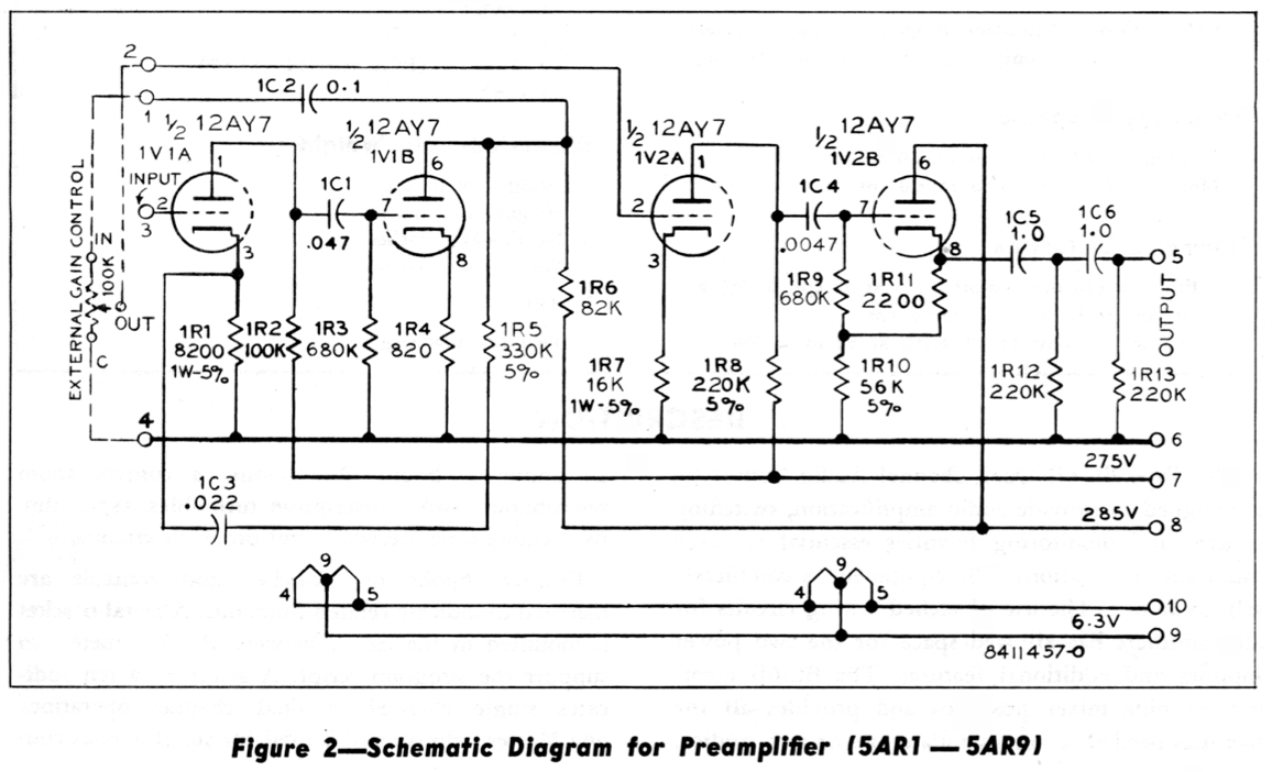
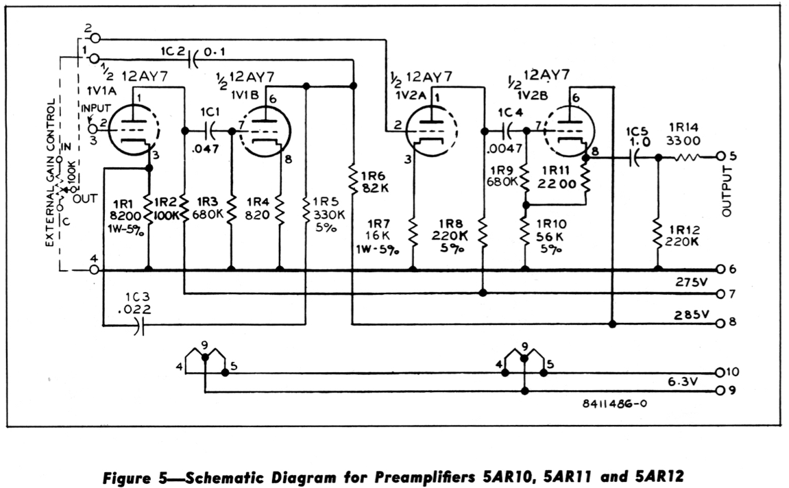
Cathode follower will have more headroom into a higher value load.  If you clip it driving a higher load, it may sound more pleasing than when driving a lower load.  Original is a high load, no transformer. 

The console PSU shows elevation of filament.  It's not required. 

Power filtering; do the math comparing number of channels versus stock console PSU/channel count.  Really lots of leeway.

My gain tests were done with (2) 10mfd filter caps and 100K between them, 1K input isolation resistor. 
RCA console method is a 10K iso resistor feeding 40mfd feeding 22K feeding 40mfd for every 5 preamps in parallel. 
Equate to 20K/20mfd/50K/20mfd for 2 preamps, or 40K/10mfd/100K/10mfd for 1 preamp:

picture link

 
Thanks a lot for sharing all this information, there are some good hints in it. Have to get some time for more reading.
I thought about power filtering; it is 1ch, HT and heater psu are both well regulated, so ripple is very very low. What got me thinking about decoupling caps are some other preamps, but when i think about it i can't find a reason to add them here. That little difference between two HT's shouldn't make difference for one channel.
CF are interesting; many people don't like them, but in my trials they sounded neutral into 10k loads (don't remember if i tried lower). I've seen potential dividers for setting grid voltage, it seems like biasing it from cathode has few advantages, but i really didn't come that far to judge which is better. Maybe it is just Gates vs RCA, or some other way, don't know..
 
Chiming in to say thanks @emrr for those sweeps and xfmr info, 10 years later! I traded for a pair of these input transformers recently and after installing one in a preamp build have noticed the same HF rolloff issues with a line to mic pad when sending sweeps through. Wasn't sure if it was something on my end but your info has proven a good resource
 
Yet another old thread resurrection!

Thank you EMRR for all of this insight.
I’m in planning stages to build some point to point versions of these modules, maybe a couple pre’s and a couple boosters and line amps, to also function as a summing mixer/amp. If all goes well, could tack on more channels. Tube count would get high, and current draw.

The big question is choosing a power supply to hopefully fall in place seamlessly with these circuits. I couldn’t find any specs for the supplies (2) they used for the BA-6x. I’d really like to build their monitor amps too, to have a nice set of speaker outputs in general. Those draw probably 40mA each though, as opposed to the other modules.

Any recommendations on a company that makes good enough quality tube amp power transformers for these circuits? Is something like Edcor worth considering? They have exactly a 365-0-365 but it’s only 120mA on B+ and 2A on the 5V which might not be enough, not to mention the filament draws. But maybe their 220mA 360-0-360 linked here would be managable with a few minor resistor value adjustments in the circuits? Or maybe it’s close enough already?

https://edcorusa.com/products/xpwr0...0ma-6-3v-7a-5v-4a?_pos=1&_fid=3188e733c&_ss=c


I put the input transformer on that schematic using Photoshop once when I was selling a bunch on ebay, so copies like that floating around came from my auction. I scanned it originally from a BC-3C manual.

Another piece of the puzzle is the existence of three input transformer revisions. There's a silver cased that says 'made by RCA', then the UTC with the same part # plus UTC #, then a UTC with M-8366A marking.

The first output cap would leak enough to cause clicks, because when a preamp is assigned to the center there's no load, to draw down leakage at all. Many modern caps with no load also exhibit a leakage voltage.

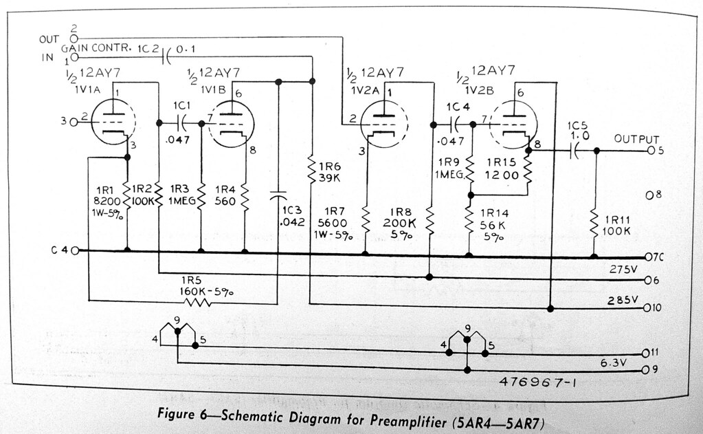
The BC-6B manual scan I have is 73.4MB. From it I have the following two variations, only difference being the extra output cap. These boards are both marked 643262-1. SUB-0.

9037868114_618688b6a1_o.png


9037869120_589ff17f01_o.png


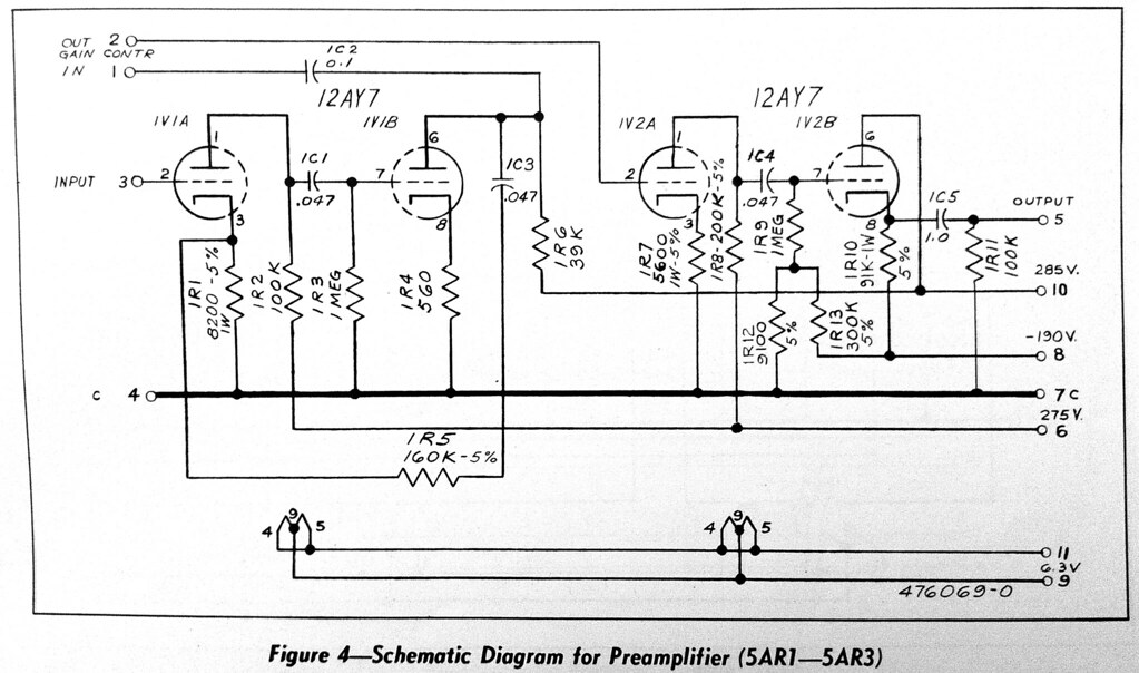
All the caps on the unit I measured today were replaced, so I was uncertain if any changes were made. There are no board markings of an kind. Now that I drew it out, I found a BC-3B manual I forgot I had, and I see 1C3 marked as 0.047 on one board, and 0.042 on the other. I see there the more descriptive sentence regarding gain, which explains the BC-6B manual being a poor transcription/edit.

From it I have the following two variations, which I hadn't really looked at before. I see also the PSU has 6.3 winding dedicated to a 6X4 to generate the -190V bias you mentioned. The BC-3C manual matches the BC-6B manual regarding the PSU, and lack of bias rectifier. I would guess the negative bias was still found unsatisfactory, or the bean counters decided the extra caps were the less expensive approach for continuing production. Probably the expense angle.

9035766303_358de65918_b.jpg


9037992724_22a965c583_b.jpg
 
For a simple, highish current HT supply I use 1:1 toroids with split primaries and secondaries because they are reasonably easy to find. You can parallel or series connect the primaries for US/EU mains voltages and the pair of, usually, 115V secondaries in series give you a raw dc starting point of about 340V unloaded with a capacitor input semiconductor rectifier. The TRIAD VPT230-220 is a 50VA type which can provide well over 100mA of HT or the VPT230-430 is the 100VA version capable of twice as much.

Cheers

Ian
 
Last edited:
I prefer to use toriodal power transformers, made to individual specs. They are worth the money, are completely silent and I order them with magnetic and electrostatic shielding. Of course, they are a little more expensive compared to standard types, but they provide what is needed exactly. I had problems with conventional core types as mechanical noise, hum and stray fields. Especially when using in tube preamps. I never use that type since.
 
No, I don't have a link but I do have a pdf of the manual. It is 70Mbytes big so I don't know if I can email it direct to you. Alternatively I could make it available via yousendit.com
[I do have a pdf of the manual. It is 70Mbytes big so I don't know if I can email it direct to you] -- I could give you access to one of my online web-storage folders so you could upload it and then I could provide a link to that folder so someone else could download it. >> NOT A BIGGIE!! <<

/
 
I prefer to use toriodal power transformers, made to individual specs. They are worth the money, are completely silent and I order them with magnetic and electrostatic shielding. Of course, they are a little more expensive compared to standard types, but they provide what is needed exactly. I had problems with conventional core types as mechanical noise, hum and stray fields. Especially when using in tube preamps. I never use that type since.

Where do you order from and get them to your specs?

I took a look around and it doesn’t seem easy finding a way to order something toroidal like a 730V, 6.3V, 5V setup with plenty of current at each, and center taps where needed. I suppose I could put two 365V toroids opposite each other to total 730 to create the high rail with decent current, and maybe similarly get pairs for totaling 5V and 6.3V. Then I’d have all my center taps too. That sounds pretty expensive though.

Regardless, I’m assuming I’ll just make this an external supply that will never get mounted inside any chassis. Maybe that helps alleviate some of the proximity issues with conventional cores and so then could use an Edcor since it’s external? Or do toroidal units ALSO send cleaner power rails?

For reference, below is the power circuit for the BC-3, as opposed to the BC-6, since the BC-6 contains the -190 V rail which doesn’t seem necessary since RCA revised that approach into the units only briefly and removed it.

And the 24V is i believe just for light bulb indicators.

IMG_0186.jpeg
 
FYI:

https://www.btbtransformers.com/transformers/
BTB offers:
- New transformers as manufacture-to-order
- Used or surplus transformers for immediate delivery
- Distribution, power, and special application transformers
- Both standard and custom designs

BTB offers transformers as manufacture-to-order or from stock, delivering both standard and special applications ordered as single units or in bulk. As we’re not bound by a single factory’s production range or capacity, we are free to adapt to what you need and when you need it.

Flexible, efficient, and reliable. This is BTB Transformers.

When you’re looking for great customer service, broad expertise, and high-quality, long-lasting transformers, BTB is who you call. Not bound by a single factory’s production range or capacity, we are free to adapt to what you need and when you need it.

If you need a transformer ASAP, don’t hesitate to contact our emergency services, or browse the extensive inventory list on our website to find transformers available for immediate delivery.

Custom Design:

The customization process covers everything from both electrical and mechanical design parameters to the level of accessories and instrumentation. This gives us full freedom to meet special requirements, such as impedance, level of losses and noise levels. It also gives us the possibility to fit the transformers into places with space restrictions.

Custom designs are made to order and handled as individual projects to ensure that all specific requirements are met.

Send a request for Quotation:

Please share your contact information so we can reach you if needed. Information shared is not shared with third party and treated as personal data.

https://www.btbtransformers.com/contact/rfq
>> YOU'RE WELCOME!!!

/
 
Last edited:
[I do have a pdf of the manual. It is 70Mbytes big so I don't know if I can email it direct to you] -- I could give you access to one of my online web-storage folders so you could upload it and then I could provide a link to that folder so someone else could download it. >> NOT A BIGGIE!! <<

/
Hi Jerry, that post was made back in 2011 - I sent the guy the manual by yousendit.com. Do you want a copy for yourself?

Cheers

Ian
 
I prefer to use toriodal power transformers, made to individual specs. They are worth the money, are completely silent and I order them with magnetic and electrostatic shielding. Of course, they are a little more expensive compared to standard types, but they provide what is needed exactly. I had problems with conventional core types as mechanical noise, hum and stray fields. Especially when using in tube preamps. I never use that type since.

I believe I’ve settled on a toroidal to get for this..
https://www.antekinc.com/as-4t360-400va-360v-transformer/
It has 4 secondaries.. a pair of 360’s at 500mA each and a pair of 6.3’s at 4A each. I can create a 360-0-360 at this 500mA.
The 6.3’s I can wire in parallel for a total of 8A for filaments on one supply, or I can have two to separate some tubes from each other.

My question is this.. in the context of the BC-5/6 power schematic, how should I anticipate the rated / estimated 360 V of the toroidal comparing to the 365 V noted in the RCA schematic? If you look at the spec sheet of the toroidal above, you’ll see that there is a test reading under no current draw and a test reading under too much current draw. The no draw spec is coincidentally 365. I know this is all splitting hairs and that any given supply still have a certain tolerance range, but I’m curious… would RCA in their schematic note 365 to mean under typical current draw or would they mean that their transformer puts out 365 when zero current draw/load? Bascially im wondering if maybe I should get a toroidal that’s putting out a little higher voltage when not putting out current, so that when it drops down it’ll be “365”.
Also, is it safe/realistic to power up a toroidal and take measurements of the leads alone? Obviously assuming extreme safety and care, since this is 720 volts, so proper fasteners and connectors would be fixed in place. But does a toroidal need to only be tested for voltage under a real load for the reading to make any sense ?
 
I'd ignore the 360 vs 365 as power line tolerance is at least +/-5% anyway. Of bigger concern is should you replace the 5R4 with two solid state devices, as silicon diodes do not have the voltage drop associated with a vac tube rectifier. You will then likely need to add some resistance in series with each rectifier diode to bring the B+ down to what the schematic indicates, e.g. 300V on B2 when measured under load. The added resistance approximates the 5R4 so this does not adversely affect supply regulation.

FWIW With silicon rectifiers as cheap as they are you could consider moving to a full-wave bridge rectifier configuration with a 360-ish volt transformer, no longer requiring a 700+ volt center-tapped transformer.

When testing a HV transformer consider using 12V AC on the 120V primary, now things are much safer and just scale all your readings by a factor of 10. And yes, it is safe to not have a load on the transformer.
Great point about 12VAC, thank you! I’ll bring it down to 1/10 scaled testing. Maybe a variac is a bad idea though, given that the toroidal already introduces its own inrush current. That could make for TWO devices causing inrush together.
As for the rectifier tube… For fun, I’m just recreating the original power circuit. I already have the tube and grabbed a good 5VAC power transformer for cheap. Will be fun to be able to say it is the original core power design. Whether or not that has any bearing on the overall sound, maybe so maybe not!
The only real complication is confirming i have some math correct for the rails. Been reading through @emrr ’s notes in this thread, but RCA has some confusing labels for their rail voltages on pcb’s vs on power supply. B3 / B4 on power schematic are labeled 290/265. B3/B4 on preamp schematic are labeled 285/275. It’s consistent, and the same for both the BC-5 and BC-6.
Emrr also came up with a run down of the RCA maths:

“My gain tests were done with (2) 10mfd filter caps and 100K between them, 1K input isolation resistor.
RCA console method is a 10K iso resistor feeding 40mfd feeding 22K feeding 40mfd for every 5 preamps in parallel.
Equate to 20K/20mfd/50K/20mfd for 2 preamps, or 40K/10mfd/100K/10mfd for 1 preamp”

But I’m not quite following it so need to decipher. He posted that photo of his preamp pcb, up at the top of this page, which helps a lot to see something functional for one pcb at least. I suppose it might be possible to just repeat that across all of the other preamp pcb’s. I’m going to start with building just one or two, but would like to design this for 8 preamps.
 
When thinking about supply voltages there are a couple main issues. One is impedance, whose main purpose is mitigating crosstalk, and accuracy, as needed to support precision. Audio amps are seldom precision so accuracy is not the issue. +/-5% is likely more than good enough, that translates to +/-13V at 260V DC. So 265V and 275V are roughly the same. Remember this is an unregulated supply, the preamps were designed to accept the resulting voltage variation.

When it comes to impedance and crosstalk that is where the filter capacitors and series resistors do their work. The cap gives a relatively low impedance across the audio frequencies, while the series resistors are much higher to provide isolation. Actual preamp output power is small, noticeably less than the steady-state preamp power dissipation, so audio level has a minimal effect on supply regulation, as the filter caps do their job and the DC load current varies only a small amount. The drop on the series resistors will vary with the number of preamp loads, so it is good to run with a representative number of preamps to keep the supply voltages down in the range where they belong. If you can't do that either raise the supply series resistors or add dummy loads. Your call on that.

Emrr was just doing the "raise the series resistor" approach for fewer than 5 preamps, along with keeping the "resistor x capacitor" product about the same. That keeps the -3dB point of the supply filter constant even though the component values change to suit the number of preamps fed.
 
Last edited:
When thinking about supply voltages there are a couple main issues. One is impedance, whose main purpose is mitigating crosstalk, and accuracy, as needed to support precision. Audio amps are seldom precision so accuracy is not the issue. +/-5% is likely more than good enough, that translates to +/-13V at 260V DC. So 265V and 275V are roughly the same. Remember this is an unregulated supply, the preamps were designed to accept the resulting voltage variation.

When it comes to impedance and crosstalk that is where the filter capacitors and series resistors do their work. The cap gives a relatively low impedance across the audio frequencies, while the series resistors are much higher to provide isolation. Actual preamp output power is small, noticeably less than the steady-state preamp power dissipation, so audio level has a minimal effect on supply regulation, as the filter caps do their job and the DC load current varies only a small amount. The drop on the series resistors will vary with the number of preamp loads, so it is good to run with a representative number of preamps to keep the supply voltages down in the range where they belong. If you can't do that either raise the supply series resistors or add dummy loads. Your call on that.

Emrr was just doing the "raise the series resistor" approach for fewer than 5 preamps, along with keeping the "resistor x capacitor" product about the same. That keeps the -3dB point of the supply filter constant even though the component values change to suit the number of preamps fed.
Understood, thank you! That all makes sense. If i have it all correct conceptually…. No matter where the filters are, be it at each card or at the power supply to feed multiple cards, for these preamps there will be an RC filter providing DC for one rail, and a second in series RC filter providing DC for the second slightly lower rail. The voltage doesn’t matter a lot, the separation is the point. And in Emrr’s explanation, he refers to RCA’s method of 10K/40uF, then 22K/40uF. Those two outputs are designed to power 5 cards in parallel. That all sounds straight forward. AND, one can find those two sets of RC rails in the power schematic shown above on this page. However, where I get hung up is when evaluating RCA’s preamp schematics and looking at the pins pages…
https://www.steampoweredradio.com/pdf/rca/manuals/RCA Type BC-5B Audio Consolette Manual.pdf
If you scroll down to the full schematic you’ll see notes that the preamps are fed B3/B4. But if you look back at the power schematic again, you’ll see that the two sets of rails that we just discussed, with those 10k/40uf/22k/40uf sets, are labeled B6/B5 and B8/B7. So I think maybe there are B(#) labeling errors in the total schematic where they label the B+ points reaching cards. But I do need to clarify all of this because I plan to also build a pair of Program amps and a pair of Monitor amps. So, what’s interesting is that B3/B4 are fed by large caps… 80uF and 120uF. Maybe that pair is supposed to feed the Program amp and Monitor amp? That would also make sense since those rails are higher upstream, and from what I’ve learned of tube rails is that the further downstream rails are used for more sensitive amp stages.

Id like to, in the end, make this an 8 preamp, L/R program “booster amp“, L/R Program Output Amp, and possibly a L/R Monitor Output Amp. Essentially an 8 channel traditional stereo console with some faders/panniers before booster stage. I would prefer to build just one or two preamps to start, but would have to make dummy loads for the rest of the modules in order to build incrementally in an organized fashion. So the challenge would be coming up with a total dummy load value for each type of module, pop in high watt resistors in place of total circuits that are still missing, and then I’d be able to stabilize the power design at least.
 
The full schematic agrees with the power supply. B3 & B4 feed 5 preamps, so they have 1K and 6K8 isolation resistors. B5 and B6 feed only the (one) program preamp, so 10K and 22K isolation resistors. B7 and B8 feed only the (one) monitor preamp, so again 10K and 22K isolation resistors. B1 feeds the program amplifier, kind of medium power, so a 3K isolation resistor. B2 feeds the monitor amp with a beefy speaker driving output, so only a 750 Ohm isolation resistor. I didn't look at the accompanying caps to figure the -3dB points, but be aware the pgm and mon amps have higher signal levels so they need less filtering to achieve the same signal to hum ratio. They also have better output side hum rejection since their output stages are push-pull.
 
The full schematic agrees with the power supply. B3 & B4 feed 5 preamps, so they have 1K and 6K8 isolation resistors. B5 and B6 feed only the (one) program preamp, so 10K and 22K isolation resistors. B7 and B8 feed only the (one) monitor preamp, so again 10K and 22K isolation resistors. B1 feeds the program amplifier, kind of medium power, so a 3K isolation resistor. B2 feeds the monitor amp with a beefy speaker driving output, so only a 750 Ohm isolation resistor. I didn't look at the accompanying caps to figure the -3dB points, but be aware the pgm and mon amps have higher signal levels so they need less filtering to achieve the same signal to hum ratio. They also have better output side hum rejection since their output stages are push-pull.
Ok thanks for the help! I understand a bit better now. I think I have been confused about the notion that 10k/40uf/22k/40uf was meant for preamps, 5 in that instance, because that is what Emrr had noted. But perhaps that’s just a faulty note.
Looking at the larger BC-6A this time, there is a similar distribution but with some different values of course.
https://www.worldradiohistory.com/Archive-Catalogs/RCA/RCA-BC-6A-Console.pdfAnd all 9 preamps are fueled by B3/B4. So when Emrr mentioned that RCA’s method was to set up rails for just 5 preamps and then add another set for 5 more, I was looking for that and couldn’t find it.
So basically the BC-6A configuration of RC isolation filters is actually pretty darn close to what one would need to make an 8 channel board with pairs of the other stages. It has that -190V rail which can be ignored essentially, but otherwise there is almost the full set complete there to work with. A few sections would need one more or one less module implemented into the load.
Any guess as to what one single preamp‘s total load would be? Or how to calculate it? Sounds pretty tricky. But I think I need to figure the loads of all of the modules out eventually in order to conclusively design all of the RC stages for the whole system at once.
 
Back
Top